Transmission illumination system for optical microscope and optical microscope using same

An optical microscope and transmitted illumination technology, applied in the field of optical microscopy, can solve the problems of inability to realize transmitted illumination and arbitrary turning of the optical path, inability to use a microscope illumination system, and no light source focusing effect, avoiding harmful effects, ensuring light intensity, The effect of high utilization of light energy

Inactive Publication Date: 2007-03-14
HEBEI UNIV OF TECH
View PDF1 Cites 10 Cited by
  • Summary
  • Abstract
  • Description
  • Claims
  • Application Information

AI Technical Summary

Problems solved by technology

This system is only suitable for ordinary light source lighting, and cannot be used for microscope lighting systems, and does not have the function of light source focusing; the patent document "An Optical Microscope Concentrating Illumination System (87202450)" discloses an optical microscope concentrating lighting system, It can realize incoherent light illumination and eliminate the diffraction phenomenon of tiny objects caused by coherent light or partially coherent light illumination. In the system, the diffuse transmission plate is added to overcome the diffraction phenomenon of tiny objects caused by coherent light or partially coherent light illumination,

Method used


Image

  • Transmission illumination system for optical microscope and optical microscope using same
  • Transmission illumination system for optical microscope and optical microscope using same
  • Transmission illumination system for optical microscope and optical microscope using same

Examples


Embodiment Construction

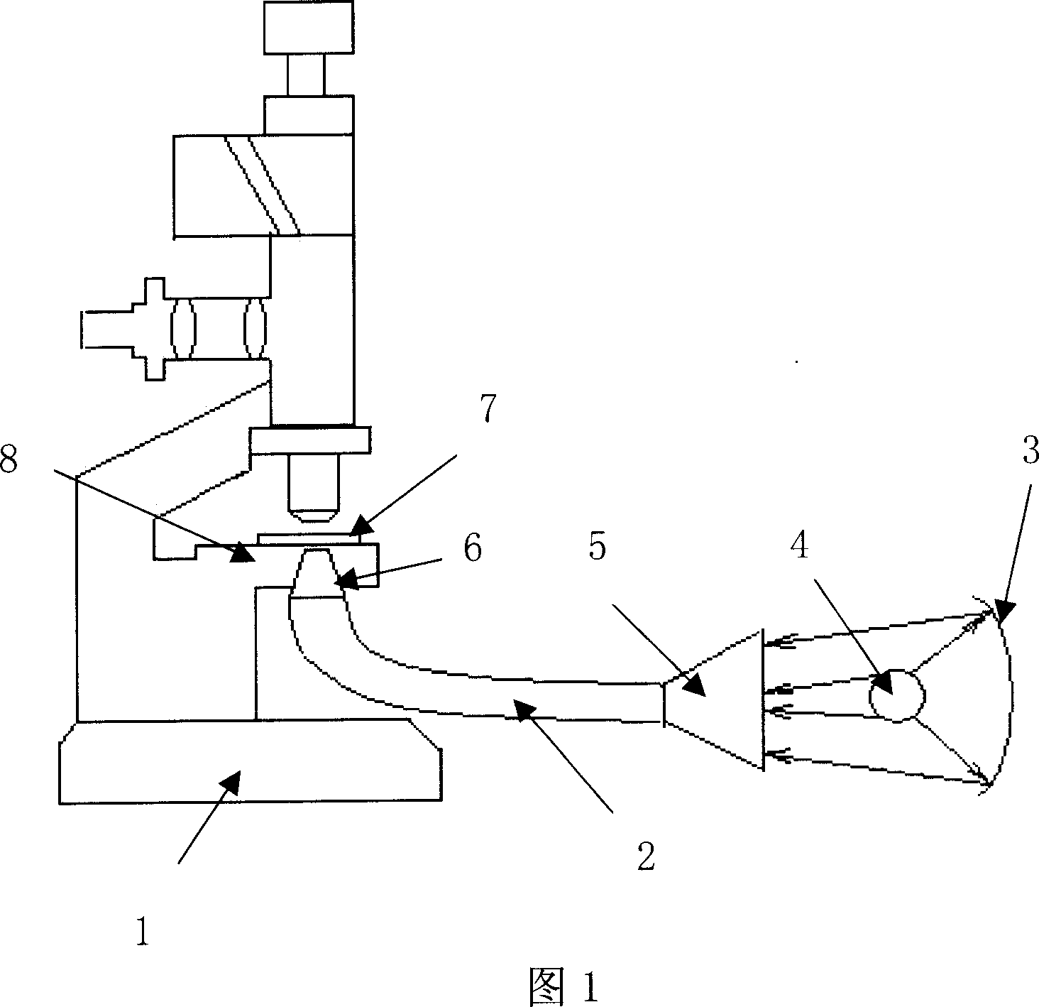
[0013] Further describe the present invention below in conjunction with embodiment and accompanying drawing thereof:

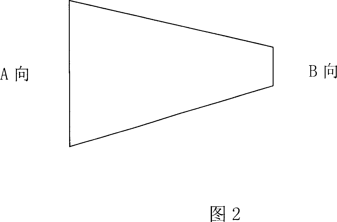
[0014] A kind of optical microscope transmission illumination system designed by the present invention (hereinafter referred to as illumination system, referring to Fig. 1-5) comprises the light source 4 in the light source box 13 and the concave reflector 3 that is positioned at its two sides and incident tapered optical fiber 5, concave surface Reflector 3, light source 4 and incident tapered optical fiber 5 constitute the generation and light collection system of optical microscope transmission illumination light source; The large end face is connected, the incident tapered optical fiber 5, the optical fiber 2 and the outgoing tapered optical fiber 6 form an optical microscope light energy transmission system; the incident tapered optical fiber 5 is fixed by the lower fastening screw 11 and the fiber holder 12 On the light source box 13; the exit tapered op...


PUM


Abstract

The related transmission lighting system for optical microscope comprises: the light source in a box, a concave reflector and an incidence taper optical fiber on sides of the light source; all three parts form the system for generating light source and focusing light. Wherein, the small end face connects with incidence taper fiber large end face by optical fiber, the incidence taper fiber, optical fiber and emergence taper fiber form the optical energy transmission system. Besides, the incidence fiber is fixed on the source box by a lower fastening screw, screw and fiber holder; the emergence fiber is fixed on the fiber fixed disk on the microscope stage by an upper fastening screw.

Description

technical field [0001] The invention relates to an optical microscope illumination technology, specifically an optical microscope transmission illumination system using a tapered optical fiber to transmit light energy and an optical microscope using it. The international patent classification number is intended to be Int.Cl.G02B 21 / 00 ( 2006.01). Background technique [0002] Traditional optical microscope transmitted illumination can be divided into two ways: critical illumination and Kohler illumination. Both lighting methods use lenses as light concentrating devices. The main disadvantage of critical lighting is the non-uniform illumination of the plane of the object. Although Kohler lighting solves this problem, there are problems such as aberration, complex structure, and heat conduction due to the use of lenses for condensing light. When designing this lighting system, the problem of optical aberration must be eliminated. Therefore, complex lens combinations are req...

Claims


Application Information

Patent Timeline
IPC IPC(8): G02B21/06G02B21/00G02B6/00
Inventor 张思祥尹树杰冉多钢翟琳娜尹霞
Owner HEBEI UNIV OF TECH
Why Eureka
Try Eureka