

Self-locking AC contactor
An AC contactor and self-locking technology, which is applied in the direction of relays, non-polar relays, electrical components, etc., can solve the problems of large power consumption, complex stability, and poor reliability, and achieve agile action, good mechanical characteristics, and low noise. small effect
- Summary
- Abstract
- Description
- Claims
- Application Information
AI Technical Summary
Problems solved by technology
Method used
Image

Examples
Embodiment Construction
[0015] The parts purchased in the market and processed by conventional methods are assembled according to the accompanying drawings and the summary of the invention to obtain the present invention.
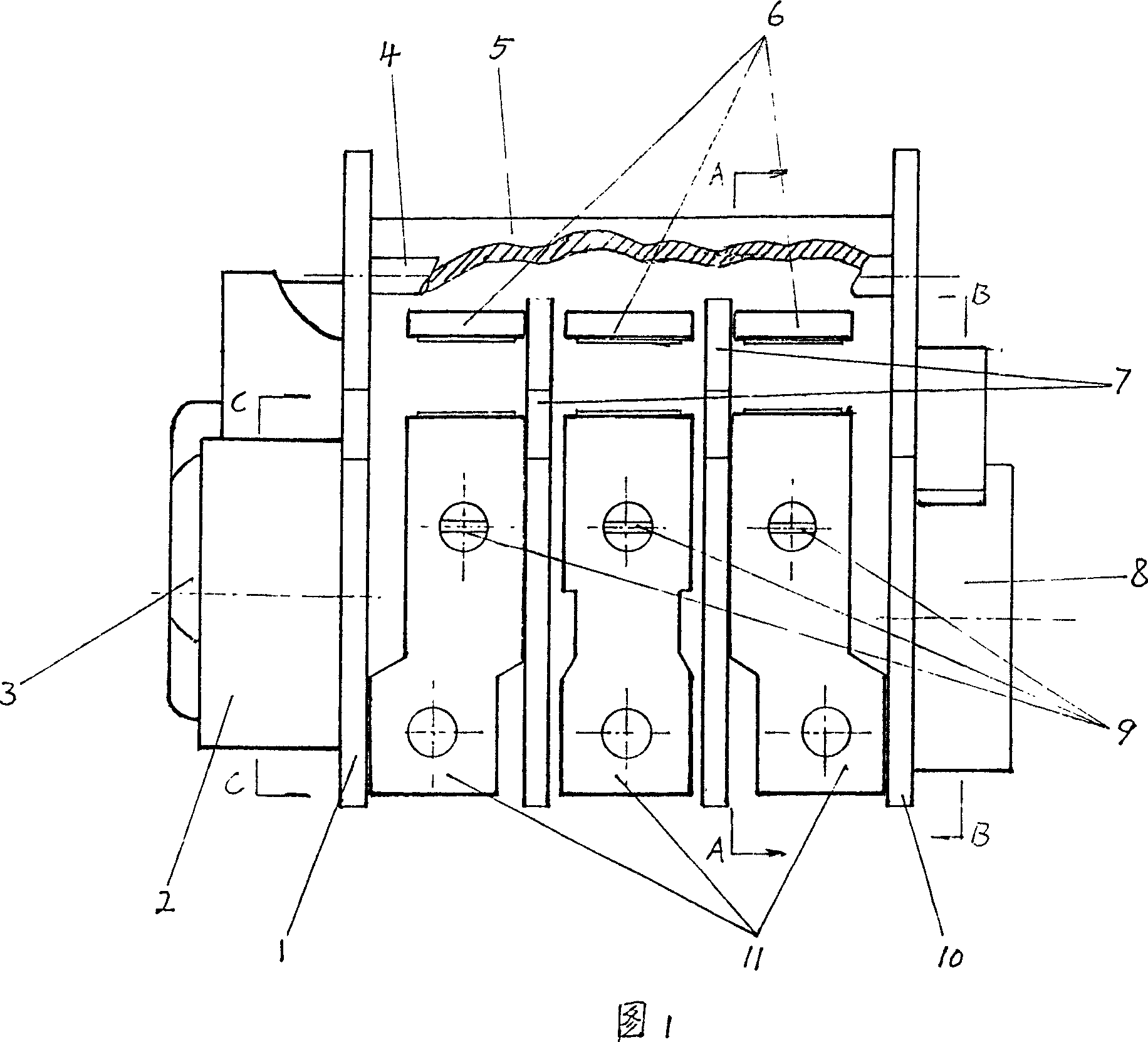
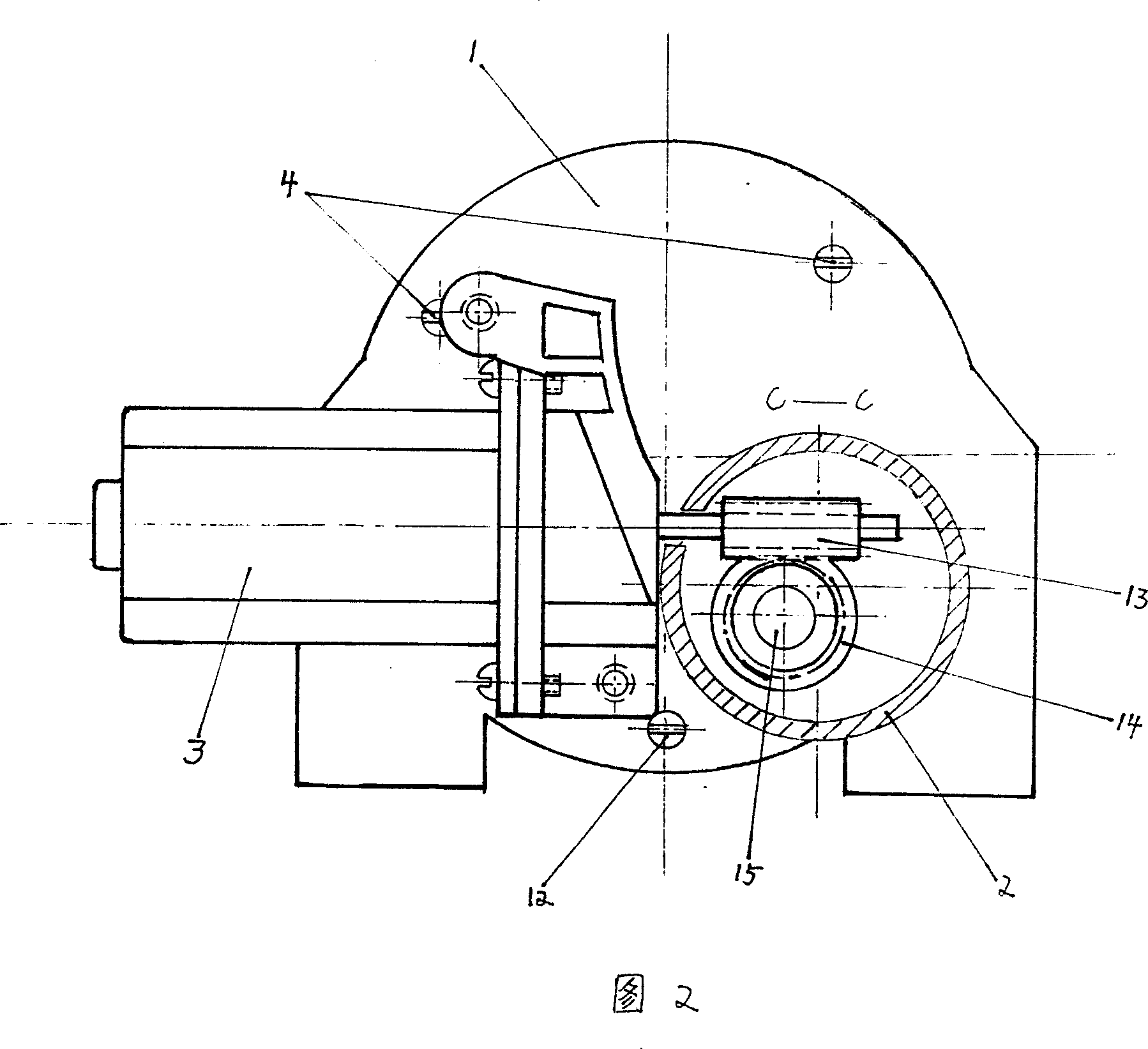
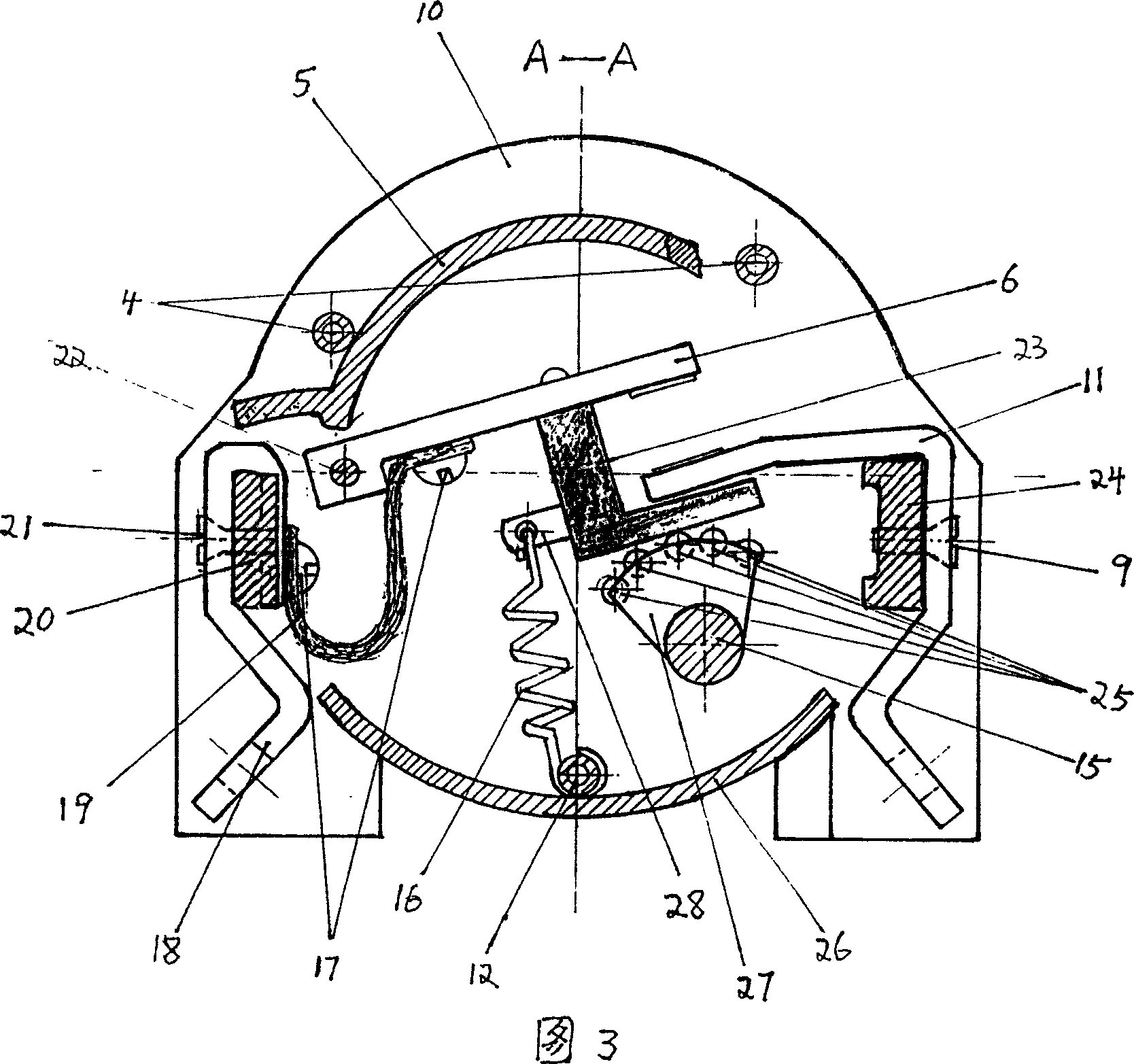
[0016] The working process of the present invention is described in detail below in conjunction with accompanying drawing:
[0017] First, connect the fixed contact (11) of the self-locking AC contactor to the controlled power supply, and the terminal (18) to the controlled device. When the 220V AC power is turned on, the power supply in Figure 6 1、2 Respectively reach the state control circuit, A-B-C-E-K-L-N and D of K-1, with the gradual completion of the charging and energy storage of the energy storage circuit, the power supply 1 And the voltage of the connected circuit is gradually increasing, and the voltage of the state control circuit changes suddenly after reaching the predetermined value, and K-1 turns on the original power supply 1 -The circuit of A-B-C-E-K-L-N is disc...
PUM
 Abstract
Description
Claims
Application Information