
Method and device for loudspeaker array setting by using quadratic residue sequence phase delay

A secondary residual sequence and loudspeaker array technology, applied to frequency/direction characteristic devices, sensors, transducer circuits, etc., can solve the problems of uneven radiation sound field and inaudible hearing, and achieve simple design method and high satisfaction Quality audio-visual entertainment, the effect of directivity improvement

Inactive Publication Date: 2007-03-14
NANJING UNIV
View PDF1 Cites 11 Cited by
  • Summary
  • Abstract
  • Description
  • Claims
  • Application Information

AI Technical Summary

Problems solved by technology

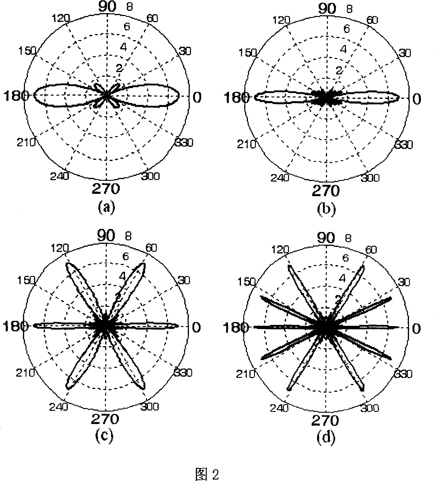
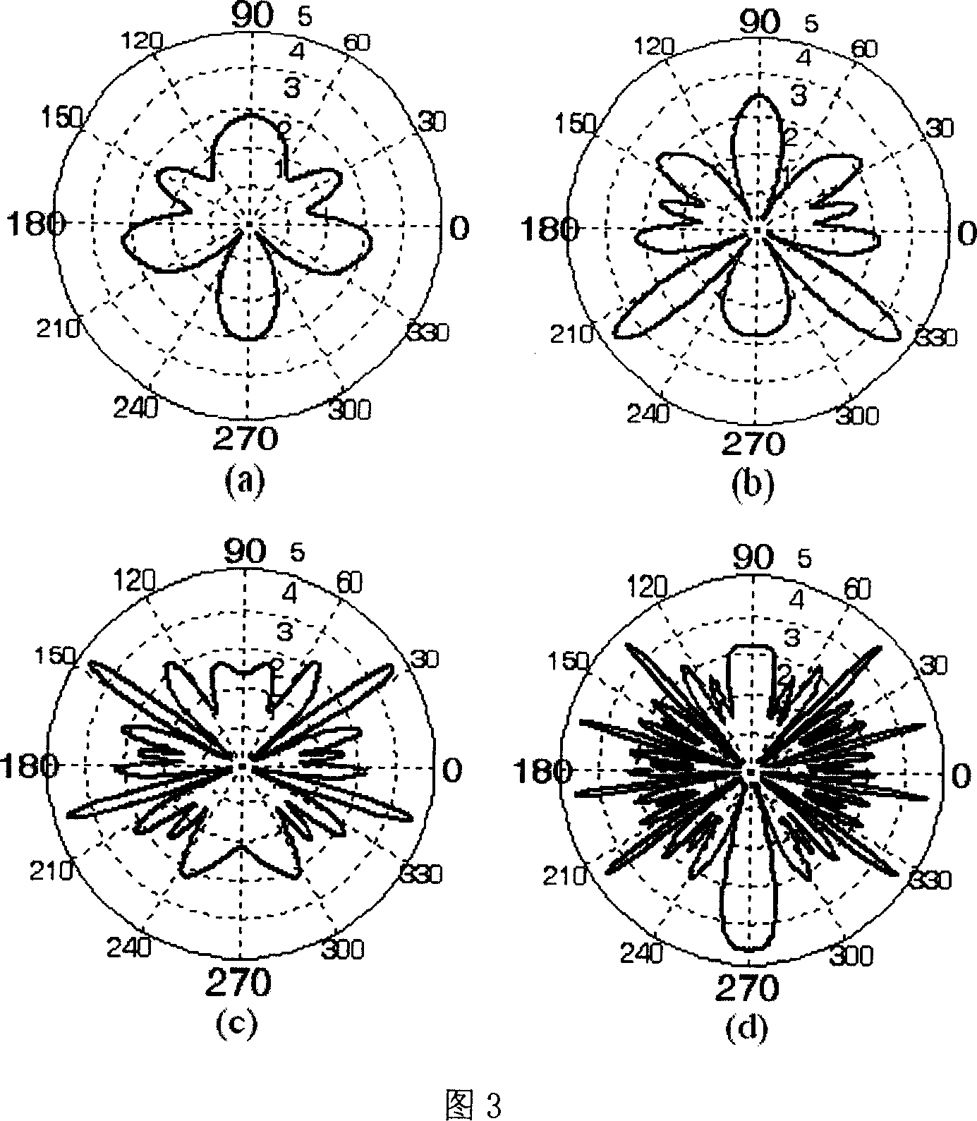
The directivity pattern (Fig. 4 is the directivity pattern of the delay time method) has relatively uniform coverage at 7000Hz, while at 8000Hz there is a wide valley point at an angle of 15 degrees, so listeners in this wide range cannot hear For the sound of this frequency, the radiation sound field is not uniform

Method used


Image

  • Method and device for loudspeaker array setting by using quadratic residue sequence phase delay
  • Method and device for loudspeaker array setting by using quadratic residue sequence phase delay
  • Method and device for loudspeaker array setting by using quadratic residue sequence phase delay

Examples


Embodiment Construction

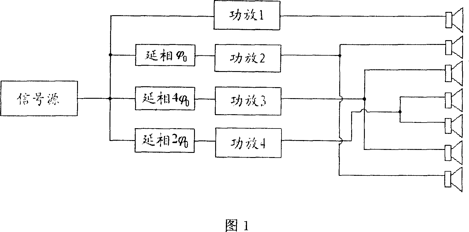
[0052] When N=7, the quadratic residual sequence is: 0, 1, 4, 2, 2, 4, 1. Then the circuit is: drive the speaker array signal source respectively through 0 , 2 π 7 , 2 π 7 × 4 , 2 π 7 × 2 , 2 π 7 × 2 , 2 π 7 × 4 , 2 π 7 The phase delay unit, after the phase delay, is amplified by power to drive the loudspeaker. Compared with the prior art, the delay of the phase delay unit is obviously not a simple proportional relationship of time delay. At this ...


PUM


Abstract

This invention relates to one method by use of second remaining sequence for microphone setting, which adopts phase time lag to realize microphone direction optimization and applies remaining sequence into microphone array. Each microphone unit feeds back different phase time lags signals to get one secondary remaining sequence.

Description

technical field [0001] The invention designs the setting method of the loudspeaker array, that is, improves the directivity of the loudspeaker array through the method of signal processing, so that it has better directivity at low frequency and high frequency, so as to improve the uniformity of the radiation sound field. Background technique [0002] In the 21st century with continuous technological innovation, in order to meet people's new demands for high-quality audio-visual entertainment, more and more large halls and venues have sprung up like mushrooms after rain. Since it is difficult for a single speaker to achieve the required and ideal sound pressure level, in these large venues and some outdoor places (such as stadiums, open squares), large-scale sound reproduction systems (speaker arrays composed of multiple speakers) are used. became an inevitable choice. [0003] Compared with the traditional sound reproduction system, the large l...

Claims


Application Information

Patent Timeline
IPC IPC(8): H04R1/40H04R3/00
Inventor 沈勇安康欧达毅
Owner NANJING UNIV
Learn More