Check patentability & draft patents in minutes with Patsnap Eureka AI!

Capsule medical device position/posture detecting system

A medical device and posture detection technology, applied in medical science, in vivo radio detectors, surgery, etc., can solve problems such as the inability to guide micro devices smoothly, it is difficult to correctly detect the orientation and position of micro devices, and capsule medical devices cannot move.

Inactive Publication Date: 2007-03-14
OLYMPUS CORP
View PDF2 Cites 23 Cited by
  • Summary
  • Abstract
  • Description
  • Claims
  • Application Information

AI Technical Summary

Problems solved by technology

[0005] However, in the position detection unit used in the movement control system of the microdevice described in the above-mentioned Japanese Patent Laid-Open No. 2001-179700, the rotating magnetic field that supplies the rotating magnetic field to the microdevice and the magnetic field based on the above-mentioned magnet interfere (mutual influence). ), it is difficult to correctly detect the orientation and position of the aforementioned tiny devices
[0006] In addition, in the movement control system of the microdevice described in the above-mentioned Japanese Patent Laid-Open No. 2001-179700, when the width or diameter of the lumen becomes smaller or narrower, or the lumen is wavy, such as the intracavity pipeline, there may be problems. Phenomenon that micro devices, etc. cannot be guided smoothly
[0007] Therefore, when the movement control system for a microdevice described in Japanese Patent Application Laid-Open No. 2001-179700 is applied to guide and control a capsule medical device moving in a body cavity, the direction change of the capsule medical device is suppressed by the lumen, Cannot always travel in the specified direction, switch directions
Therefore, when a magnetic field in the target direction is generated without taking the above into consideration, the capsule medical device may become inoperable due to the restraint of the lumen.

Method used


Image

  • Capsule medical device position/posture detecting system
  • Capsule medical device position/posture detecting system
  • Capsule medical device position/posture detecting system

Examples


no. 1 Embodiment approach

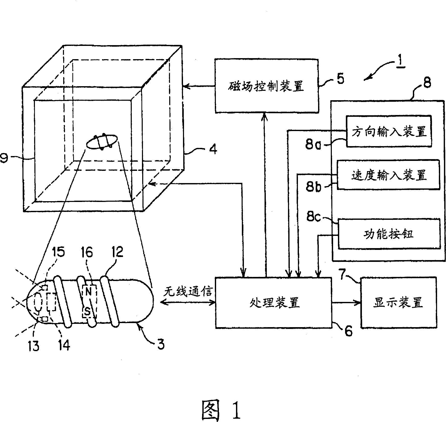
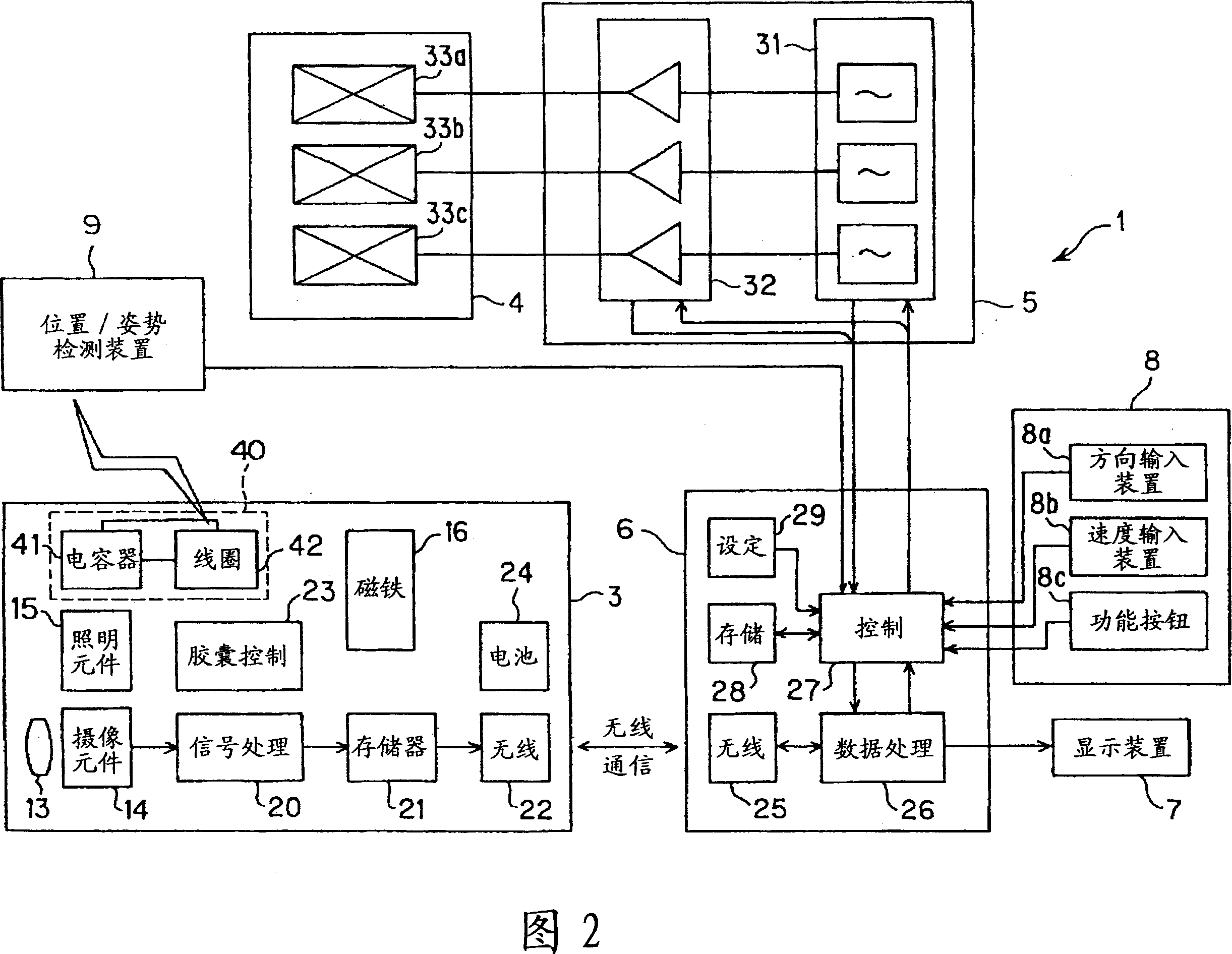
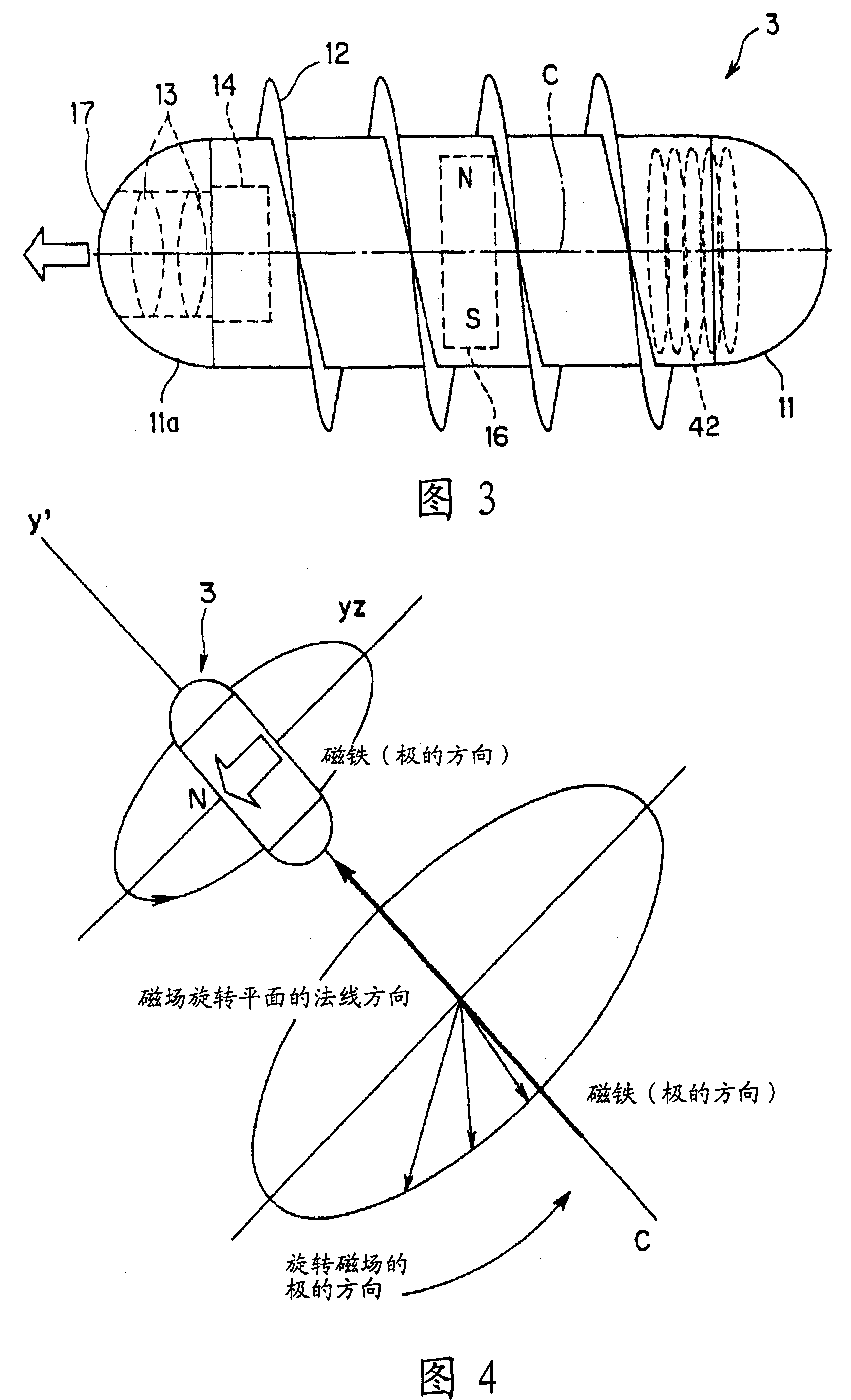
[0066] 1 to 28B relate to the first embodiment of the present invention. FIG. 1 is an overall configuration diagram of the capsule medical device position / posture detection system according to the first embodiment, and FIG. 2 is a diagram of the capsule medical device position / posture detection system of FIG. 1 . Circuit block diagram, Fig. 3 is a side explanatory view of the capsule main body, Fig. 4 is a conceptual diagram showing the applied rotating magnetic field and the action of the capsule main body realized by the rotating magnetic field, and Fig. 5 is a diagram showing the vibration applied to the rotating magnetic field in Fig. 4 A conceptual diagram of a magnetic field (magnetic field for force generation) and the action of the capsule main body realized by the vibrating magnetic field (magnetic field for force generation), Fig. 6 is an explanatory diagram of position / posture detection of the capsule body by a position / posture detection device Fig. 7 is an explanato...

no. 2 Embodiment approach

[0202] FIGS. 29A to 31 relate to the second embodiment of the present invention. FIGS. 29A and 29B are explanatory diagrams showing the rotating magnetic field generator and the position / orientation detection device constituting the position / orientation detection system of the capsule medical device according to the second embodiment. 29A is a schematic perspective view showing a rotating magnetic field generating device and a position / posture detecting device constituting the position / posture detecting system of a capsule medical device according to the second embodiment, and FIG. 29B is a schematic perspective view showing the rotating magnetic field generating device and the position / posture detecting device of FIG. 29A A schematic cross-sectional view of the internal structure of FIG. 30 is a schematic perspective view showing a rotating magnetic field generator and a position / orientation detecting device of a modified example of the position / orientation detecting device in ...

no. 3 Embodiment approach

[0211] 32 to 40C relate to the third embodiment of the present invention. FIG. 32 is an explanatory diagram showing a rotating magnetic field generator and a position / orientation detection device constituting the capsule medical device position / orientation detection system according to the third embodiment. FIG. Fig. 32 is an enlarged view of main parts of the rotating magnetic field generating device and the position / orientation detecting device, Fig. 34 is an overall configuration diagram showing the position / orientation detecting system of the capsule medical device constituting the third embodiment, and Fig. 35 is showing the third embodiment 36 is a schematic perspective view showing a modified example of the position / posture detection device of FIG. 32 , and FIG. 37 is a schematic explanatory diagram of the position / posture detection device of FIG. 36 , Fig. 38 shows the modified example of Fig. 37, is the explanatory diagram that the position / posture detection device tha...


PUM


Abstract

A detecting system of the position and the posture of a capsule medical device includes a main body of the capsule medical device that is inserted in a living body, a coil in a capsule that is arranged to the main body of the capsule medical device and forms a resonant circuit, a magnetic field generating device that is arranged around the living body and generates the Alternating magnetic field for generating an induced magnetic field in the coil in the capsule, and a plurality of magnetic field detecting devices that detect the strength of the induced magnetic field generated by the coil in the capsule by the magnetic field generated by the magnetic field generating device.

Description

technical field [0001] The present invention relates to a capsule medical device position / posture detection system for detecting the direction and position of a capsule medical device main body inserted into a body cavity. Background technique [0002] As a conventional example of traveling within a subject by means of a rotating magnetic field, there is, for example, Japanese Patent Laid-Open No. 2001-179700. In the above-mentioned Japanese Patent Application Laid-Open No. 2001-179700, a mobile control system for a movable micro-equipment is disclosed, which has: a magnetic field generator that generates a rotating magnetic field; a robot body that receives the rotating magnetic field and rotates to obtain thrust; a position detecting unit for the position of the robot main body; and a magnetic field changing unit that changes the direction of the rotating magnetic field formed by the magnetic field generating unit so that the robot main body faces a direction to reach a de...

Claims


Application Information

Patent Timeline
IPC IPC(8): A61B1/00A61B5/07
CPCA61B1/00158
Inventor 青木勳内山昭夫荒井贤一石山和志薮上信
Owner OLYMPUS CORP
Features
  • R&D
  • Intellectual Property
  • Life Sciences
  • Materials
  • Tech Scout
  • Unparalleled Data Quality
  • Higher Quality Content
  • 60% Fewer Hallucinations
Learn More