Hydraulic lifting stern platform

A working platform, hydraulic lifting technology, applied in the direction of slipway, dry dock, lifting device, etc., can solve the problems of uneven load, serious inclination of the working platform, different oil pressure loss, etc., to achieve convenient and safe operation, shortened production cycle, Avoid the effect of misuse

Inactive Publication Date: 2007-03-21
SHANGHAI JIAO TONG UNIV +1
View PDF0 Cites 19 Cited by
  • Summary
  • Abstract
  • Description
  • Claims
  • Application Information

AI Technical Summary

Problems solved by technology

There are several problems in this prior art: (1) Since the working platform is a scalene rectangle, the track and wheelbase of the rolling wheels below are asymmetrical. Readjusted by wheelbase and wheelbase, and introduces an unreliable factor to the stability when moving
(2) The 90° rotation of the scroll wheel under the workbench is done manually. When the workbench platform is switched from lateral movement to longitudinal movement, since several scroll wheels are driven by hydraulic motors respectively, if the scroll wheel rotates 90°, the hydraulic pressure will be caused. If the rotation direction of the motor is inconsistent, the movement of the workbench platform will cause great problems and dangers, and the manual operation guarantee is unreliable
(3) The four hydraulic cylinders at the four corners of the working platform are controlled by a set of oil circuits to rise or fall synchronously. On the one hand, because the oil path from the oil pipe (via) controls the valve, the length of the oil path to each hydraulic cylinder is different, ...

Method used


Image

  • Hydraulic lifting stern platform
  • Hydraulic lifting stern platform

Examples


Embodiment Construction

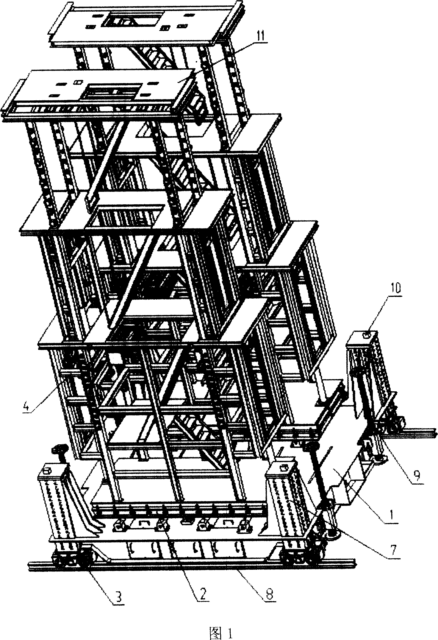
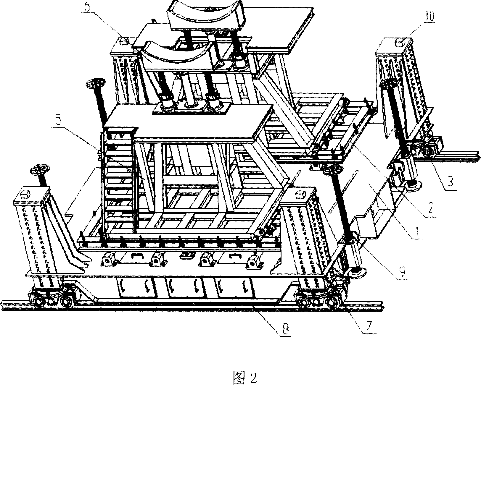
[0016] As shown in Figures 1-2, the stern hydraulic lifting work platform of the present invention includes: a work platform 1, a plane slide table 2, a rolling wheel 3, a rudder blade stand 4, and a propeller stand 5. The working platform 1 is the main body of the present invention, and the plane sliding table 2 is installed on the upper plane of the working platform 1, and the whole stern hydraulic lifting work platform is supported by the roller wheel 3, and the rudder blade stand 4 and the propeller stand 5 are respectively installed on the plane slide table 2 superior.

[0017] The rudder blade is placed on the working platform 1 and in the middle of the rudder blade stand 4 on both sides, and the propeller is placed flat on the supporting block 6 of the propeller stand 5 . A main lifting hydraulic cylinder 7 is respectively installed on the four corners of the working platform 1, which can vertically displace the working platform 1 and play the role of vertically raising...


PUM


Abstract

The present invention relates to ship building technology, and is especially one hydraulically lifting stern platform including working platform, planar slipway, rolling wheels, rudder blade floor stand, propeller floor stand and four main elevating hydraulic cylinders. Of the four main elevating hydraulic cylinders, one is the master one and the others are slave ones. There is one linear displacement sensor in each of the hydraulic cylinders for sensing the elevating displacement and controlling the synchronous displacement. The rolling wheels have separately limited rotating direction, and the rudder blade floor stand and the propeller floor stand separately for installing rudder blade and propeller are screwed to the planar slipway. The present invention is used for installation of rudder blades and propeller and can shorten installation period and raise operation safety greatly.

Description

technical field [0001] The invention relates to a device in the technical field of shipbuilding, in particular to a stern hydraulic lifting working platform. Background technique [0002] With the development of ship construction technology, the same period of ship construction, construction quality, and construction safety have been greatly improved. The tonnage of ships is showing a trend of increasing development. There are more and more types of ships, and there is an urgent need for reliable, safe, stable and simple construction. Equipment, ship rudder blades and ship propellers are the main components of ships, which are characterized by large volume and mass, with a maximum mass of more than 100 tons per piece. The installation of ship rudder blades, propellers and hulls is carried out at the stern, that is, the installation space is limited by the structure of the stern Due to the limitations of the installation, large slipways or dock door cranes cannot be used for ...

Claims


Application Information

Patent Timeline
IPC IPC(8): B63B9/00B63C5/02B66F11/00
Inventor 金鑫胡永强张轲阮士成俞海良涂宝新杨海澜肖太兴石忠贤高建文
Owner SHANGHAI JIAO TONG UNIV
Why Eureka
Try Eureka