Floor drain for co-layer draining

A technology for drainage and drainage funnels on the same floor, applied in water supply installations, indoor sanitary piping installations, buildings, etc., can solve the problems of complicated installation, high total floor drain height, insufficient water seal height and water storage capacity, etc. The effect of increased net height

Inactive Publication Date: 2007-03-21
瑞士吉博力技术开发有限公司
View PDF0 Cites 4 Cited by
  • Summary
  • Abstract
  • Description
  • Claims
  • Application Information

AI Technical Summary

Problems solved by technology

[0005] 1. The traditional floor drain is only suitable for "piping in separate floors", that is, as shown in Figure 1, the floor drain is installed on the floor of the construction floor, while the drainpipe is installed under the floor. Neighbors must be disturbed during maintenance, which cannot satisfy people's concern for the family. The privacy and security requirements of the residence cannot meet people's requirements for personalized bathroom layout and net height improvement at the same time.
[0006] 2. Moreover, the water seal height and water storage capacity of the existing floor drains are not enough (some floor drains have no water seal), and they are easy to dry up, causing the odor of the drain pipe to flood into the room
[0007] 3. The water seal can be damaged because the floor drain buckle bowl can be easily taken out, or the positive pressure in the pipeline system causes the water to float up
[0008] 4. Because the total height of most floor drains is too high, usually 100-150mm, holes need to be excavated on the floor during installation, and some even need to be pre-embedded before pouring cement. The installation is complicated and wastes manpower and material resources

Method used


Image

  • Floor drain for co-layer draining
  • Floor drain for co-layer draining
  • Floor drain for co-layer draining

Examples


Embodiment Construction

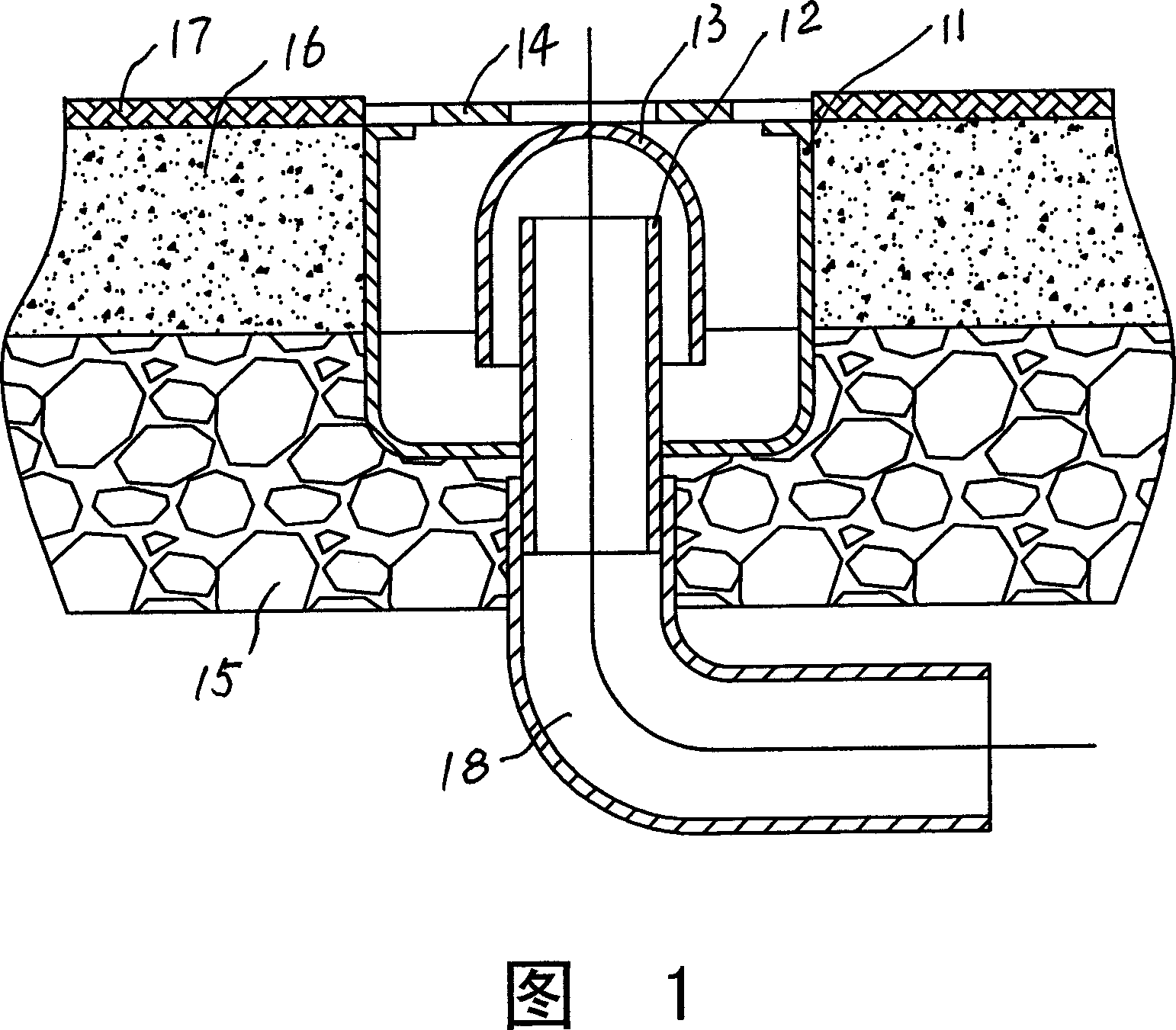
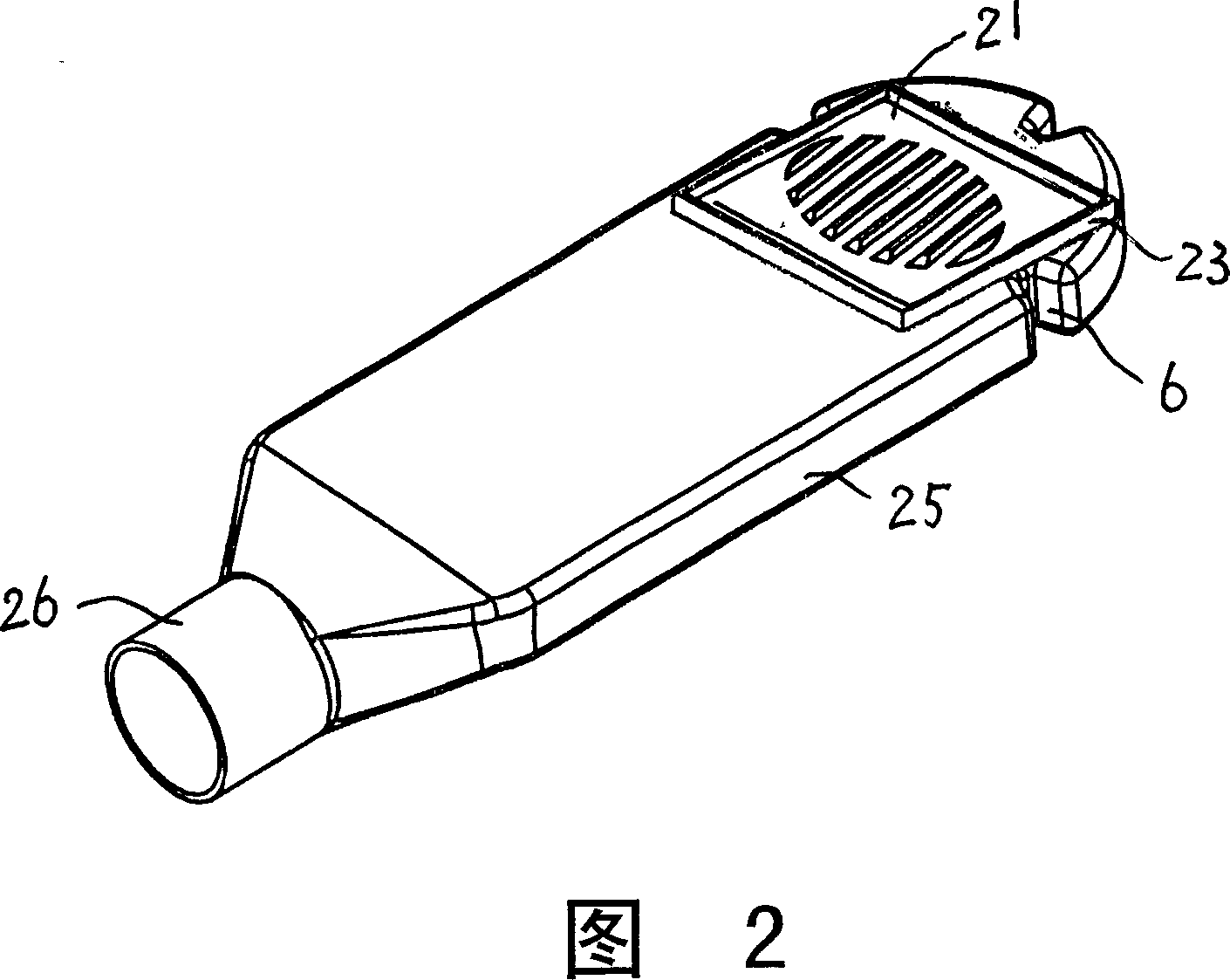
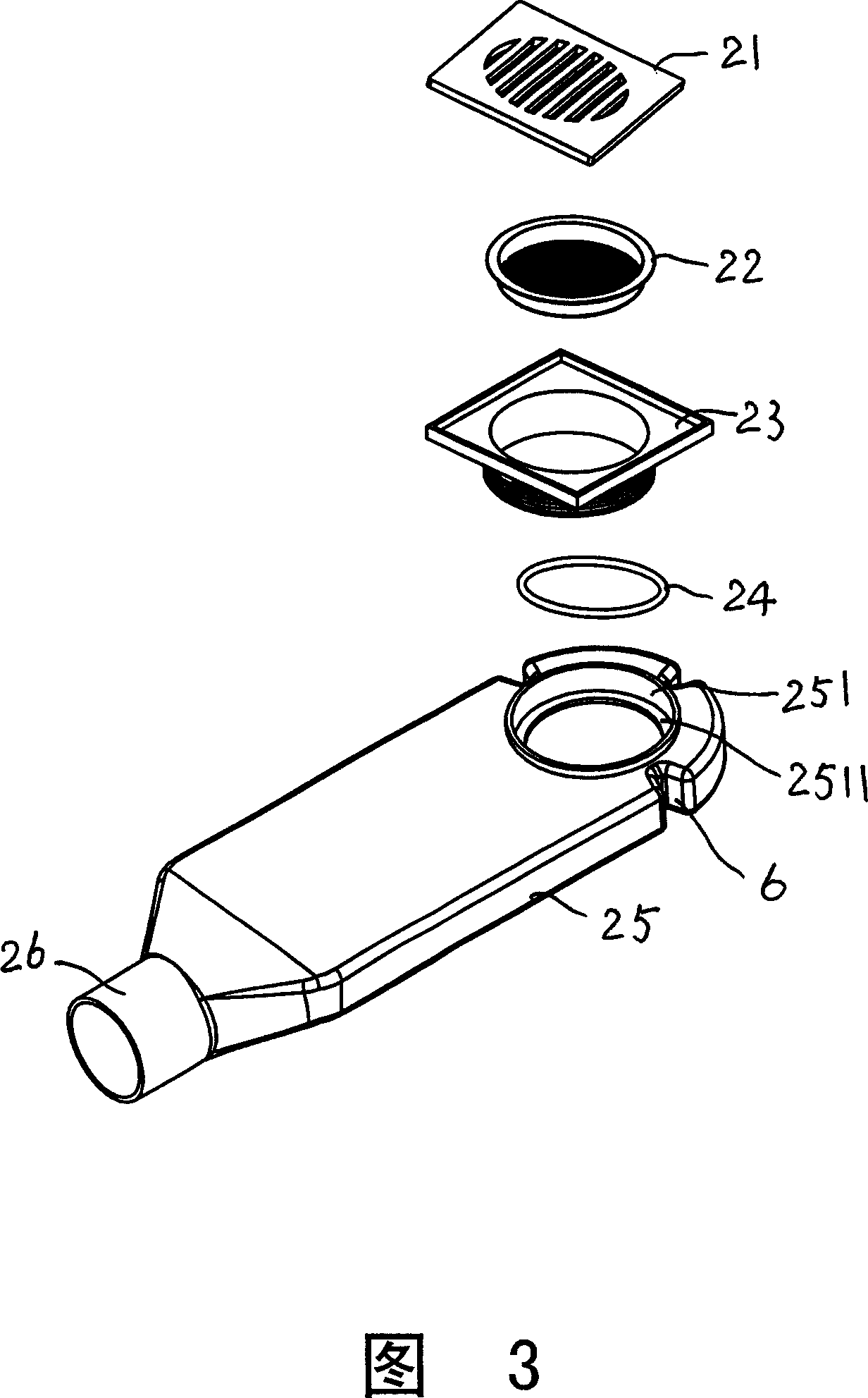
[0025] Please refer to Figure 2 to Figure 4. The present invention is a floor drain for draining water on the same floor, comprising: a grid cover plate 21 , a filter screen 22 , a drain funnel 23 , an O-shaped sealing ring 24 , and a floor drain body 25 . The grille cover plate 21 and the filter screen 22 jointly filter hair and sundries in the water. The floor drain body 25 is a hollow flat tray structure. The height of the floor drain body 25 designed in this embodiment is very low, only about 30mm, which does not affect water leakage, and takes up little ground thickness, which is convenient for installation on the same floor. The front end of the top of the floor drain body is provided with a water inlet hole 251, and the grid cover plate 21, the filter screen 22, the drainage funnel 23, and the O-shaped sealing ring 24 are sequentially seated on the water inlet hole; wherein: the described The water inlet hole of the floor drain body is a sunken tray structure, and its ...


PUM


Abstract

The present invention discloses a floor drain for same floor drainage. It includes the following several portions: grilled cover plate, filtering screen, drainage funnel, O-type sealing ring and floor drain body. It is characterized by that the described floor drain body is a hollow body tray structure, the front end of its top portion is equipped with a water inlet, the described grilled cover plate, filtering screen, drainage funnel and O-type sealing ring are successively cover-mounted on said water inlet, the tail end of said floor drain body is equipped with a water outlet, and said water outlet is connected with a U-trap pipe set in piping shaft of same floor.

Description

technical field [0001] The invention relates to an accessory of a same-floor drainage system for houses and residences, more specifically a floor drain for same-floor drainage. Background technique [0002] As an important part of the drainage system in houses, floor drains are related to people's health and environmental sanitation. [0003] The traditional floor drain structure is shown in Figure 1. This floor drain comprises floor drain body 11, sewer 12, buckle bowl 13, grille cover plate 14, and floor drain body 11 is installed in floor plate 15 and decoration layer 16, and downpipe 12 links to each other with the drainpipe 18 that is installed in floor plate 15 below. Among Fig. 1, 17 is the finishing treatment layer of ceramic tile and decoration project. After the scattered water on the ground enters the floor drain body 11 from the grid cover plate 14, it enters the drain pipe 18 through the sewer pipe 12 and is discharged. The function of the buckle bowl 13 is to...

Claims


Application Information

Patent Timeline
Patent Type & Authority Applications(China)
IPC IPC(8): E03C1/282
Inventor 周欣泳杨刚
Owner 瑞士吉博力技术开发有限公司
Why Eureka
Try Eureka