Steel plate and concrete composite beam and slab structure system

A technology of steel plate concrete and laminated beams, which is applied to floor slabs, building components, building structures, etc., can solve problems such as small spans, limited seismic use, and large section heights, so as to increase floor net heights, reduce construction costs, Improve the effect of using space

Pending Publication Date: 2016-08-03
SHANGHAI NUCLEAR ENG RES & DESIGN INST CO LTD
View PDF1 Cites 9 Cited by
  • Summary
  • Abstract
  • Description
  • Claims
  • Application Information

AI Technical Summary

Problems solved by technology

[0002] The cast-in-place floor slab has a long construction period, and prefabrication and modular construction cannot be carried out; the combined floor slab of steel beam + profiled steel plate, the combined section height reduces the net height of the room, and the fire performance is not good. The span is limited, and embedded parts cannot be reserved at the bottom of the slab
Most of the existing prefabricated beams are rectangular or T-shaped cross-sections, with large cross-section height and self-heavy weight, which are not convenient for transportation and installation, and are mostly designed according to simply supported beams; Multiple prefabricated slabs need to be arranged inside the boundary, and there are gaps between the prefabricated slabs, which are mostly designed as simply supported one-way slabs. The existing prefabricated beams and slabs have insufficient bearing capacity and integrity compared with cast-in-place structures, and there are limitations in seismic application

Method used


Image

  • Steel plate and concrete composite beam and slab structure system
  • Steel plate and concrete composite beam and slab structure system
  • Steel plate and concrete composite beam and slab structure system

Examples


Embodiment Construction

[0030] The present invention will be further described below in conjunction with the accompanying drawings and embodiments.

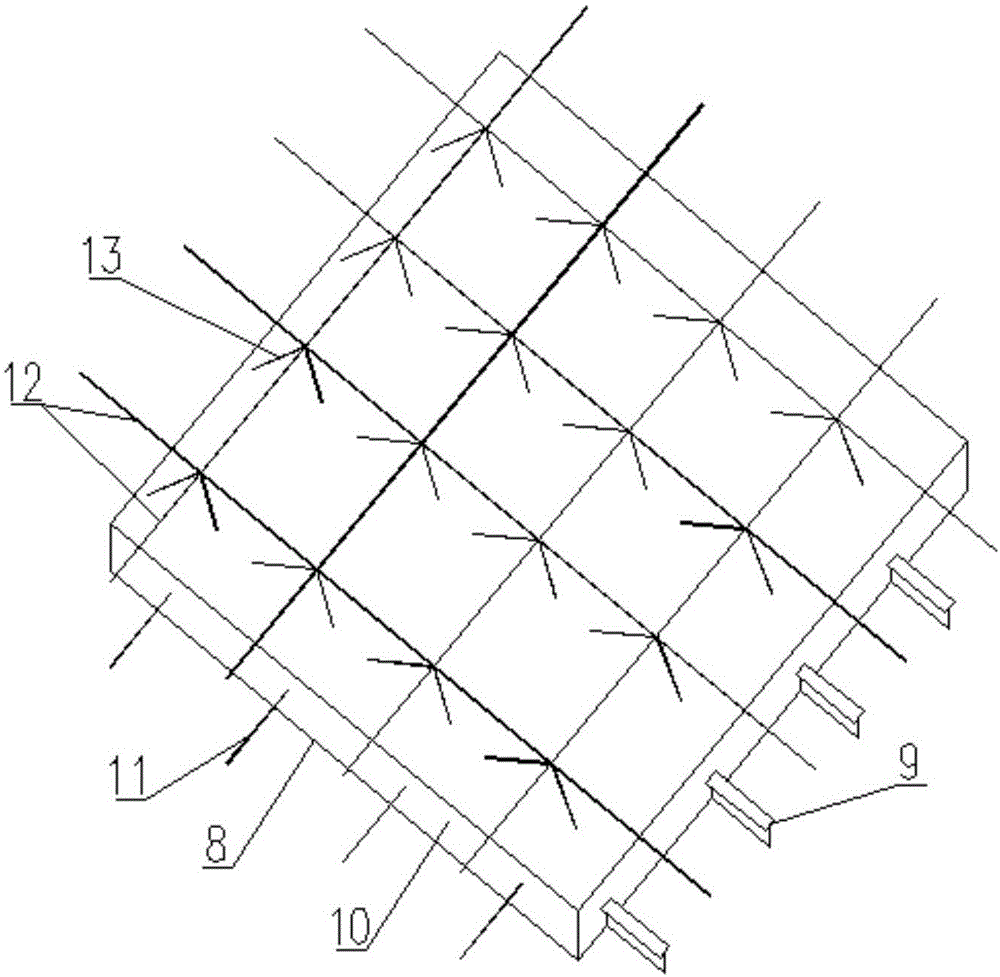
[0031] Step 1: According to the design requirements, the concrete corbel 15 is constructed on the wall column 14, and the construction joint is reserved, and the construction joint is the same as the top elevation of the prefabricated beam.

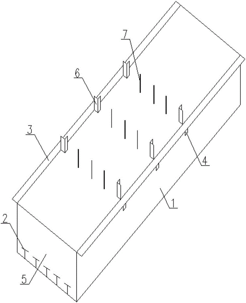
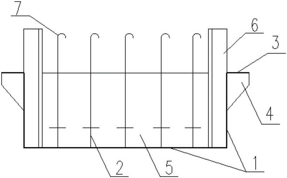
[0032] Step 2: The factory manufactures steel plate concrete prefabricated beams, and completes the installation of steel plates at the bottom and both sides of the beam 1, T-shaped steel at the bottom of the beam 2, angle steel at the side of the beam 6 and pick ears 3, longitudinal steel bars at the top of the beam 19, and tie bars at the middle of the beam 7. material; open a hole at the top of the beam side angle steel 6, weld the beam side angle steel 6 and the beam side steel plate 1, weld the pick ear 3 and the stiffener 4 at the top of the beam side steel plate; weld the tie bar 7 at the top 2 of the T-shape...


PUM


Abstract

The invention discloses a steel plate and concrete composite beam and slab structure system. The system comprises concrete brackets, a steel plate and concrete precast beam, steel plate and concrete precast plates, and a beam and slab concrete composite layer. The steel plate and concrete precast beam and the precast plates are precast in a factory; a concrete of the composite layer is poured after the precast beam and the precast plates are lift on site. The steel plate and concrete precast beam comprises a beam bottom, and steel plates at two sides, T-shaped steel at the bottom of the beam, angle steel and lifting lugs at the side of the beam, longitudinal steel bars on the top of the beam, and tie bars in the middle of the beam. Each steel plate and concrete precast plate comprises a steel plate at the bottom of the plate, T-shaped steel, unidirectional steel bars on the bottom of the plate, bidirectional steel bars at the top of the plate and diagonal steel bars in the plate. When the beam and slab structure system is under construction, the steel plate and concrete precast beam is fixedly mounted on bracket supports firstly, then the steel plate and the concrete precast plates are mounted on the lifting lugs of the precast beam, and finally, the concrete composite layer is poured on the precast beam and the precast plates. The steel plate and concrete composition beam and slab structure system has favorable integrity, and has the anti-seismic property which is coincident with that of a cast-in on-site structure; a composite part is low in sectional height and is capable of increasing a net height of a storey.

Description

technical field [0001] The invention belongs to the technical field of building structures, and in particular relates to a steel plate concrete composite beam-slab structure system. Background technique [0002] The cast-in-place floor slab has a long construction period, and prefabrication and modular construction cannot be carried out; the combined floor slab of steel beam + profiled steel plate, the combined section height reduces the net height of the room, and the fire performance is not good. The span is limited, and embedded parts cannot be left at the bottom of the slab. Most of the existing prefabricated beams are rectangular or T-shaped cross-sections, with large cross-section height and self-heavy weight, which are not convenient for transportation and installation, and are mostly designed according to simply supported beams; Multiple prefabricated slabs need to be arranged within the boundary, and there are gaps between the prefabricated slabs, which are mostly ...

Claims


Application Information

Patent Timeline
Patent Type & Authority Applications(China)
IPC IPC(8): E04B5/40
CPCE04B5/40
Inventor 马波储艳春葛鸿辉褚濛倪南左绍兵李磊
Owner SHANGHAI NUCLEAR ENG RES & DESIGN INST CO LTD
Why Eureka
Try Eureka