Air conditioner
A technology of air conditioner and air filter, which is applied in the field of indoor units, and can solve problems such as increased interval between filter guides, poor installation, and air filter disengagement
- Summary
- Abstract
- Description
- Claims
- Application Information
AI Technical Summary
Problems solved by technology
Method used
Image
Examples
no. 1 approach
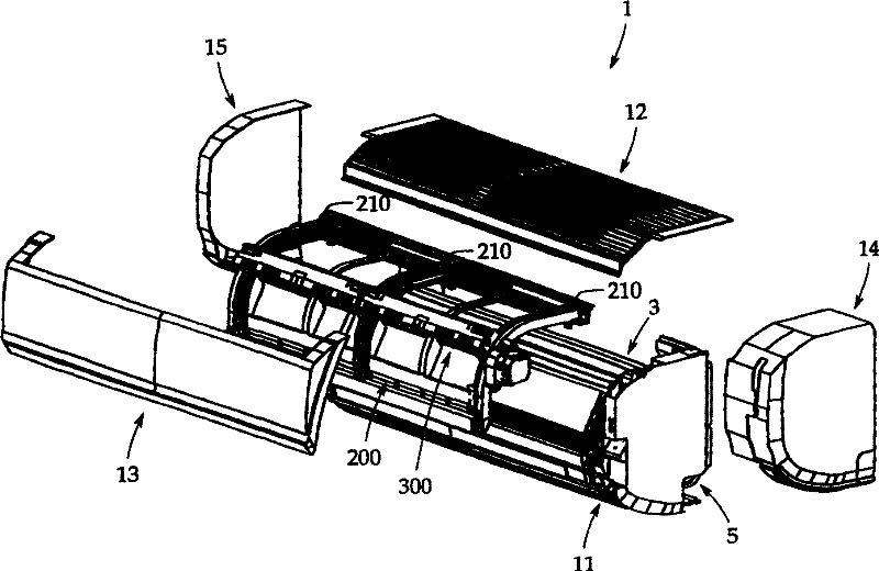
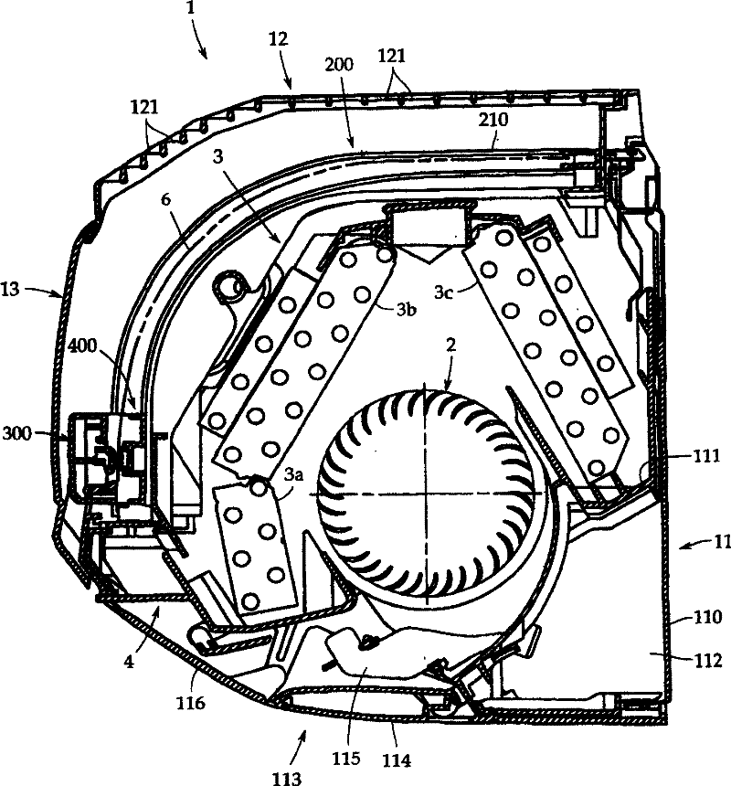
[0160] Hereinafter, embodiments of the present invention will be described with reference to the drawings. figure 1 is an exploded perspective view of an air conditioner according to an embodiment of the present invention. figure 2 is a longitudinal sectional view of the air conditioner.
[0161] from figure 1 and figure 2 It can be seen that the body casing 1 of this air conditioner includes: a backboard 110, a base plate 11, an upper panel 12, a front panel 13, a right side panel 14, and a left side panel fixed on the wall by fixing screws (not shown). Panel 15. All these parts are molded problowers of synthetic resin. The fuselage shell is combined with a transverse air flow fan 2 as a fan, a heat exchanger 3, a drain pan 4, and the like.
[0162] The base plate 11 is fixed to the back plate 110 with a pair of left and right side plates (not shown) formed to hang from both sides of the heat exchanger 3 to the wall. Between the side plates, a cross-flow fan 2 and a h...
no. 2 approach
[0235] also, Figure 18 is a perspective view of a second embodiment of the air conditioner according to the present invention. Fig. 19 is a diagram for explaining a second embodiment of the present invention; Figure 19A is its first cross-sectional view, and Figure 19BIt is an enlarged view of its main part. Figure 20 is a second sectional view of a second embodiment of the air conditioner according to the present invention. Figure 21 is a third sectional view of the second embodiment of the air conditioner according to the present invention. Fig. 22 is a diagram for explaining a third embodiment of the air conditioner according to the present invention; Figure 22A is its first cross-sectional view, and Figure 22B It is an enlarged view of its main part. Figure 23 is a second sectional view of a third embodiment of the air conditioner according to the present invention. Figure 24 is a third sectional view of a third embodiment of the air conditioner according ...
no. 3 approach
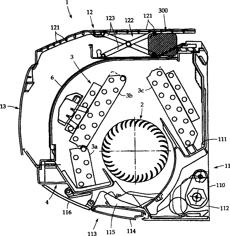
[0253] Now, refer to Figure 8 22 to 25 , a description is given of the configuration and operation as a third embodiment in which the upper panel 1001 b is forcibly opened outward in contact with the dust removing device 1007 .
[0254] from being the first state Figure 22A It can be seen that the dust removal device 1007 is configured with a dimension A from the air filter 1004 to the outside of the dust removal device 1007 housing. The dust remover 1007 is accommodated within the range of dimension B from the opposing air filter 1004 to the front panel 1001a, opposite to the lower end of the front of the air filter 1004, in a relationship of "dimension A<dimension B".
[0255] The upper panel 1001b is changed so that it can move vertically through the link mechanism 1010 provided on both sides of the upper panel 1001b, so that the dust removal device does not contact it.
[0256] In addition, the upper panel 1001b is mounted on the upper portion of the air conditioner in...
PUM
 Abstract
Description
Claims
Application Information
 - R&D
- Intellectual Property
- Life Sciences
- Materials
- Tech Scout
- Unparalleled Data Quality
- Higher Quality Content
- 60% Fewer Hallucinations
Browse by: Latest US Patents, China's latest patents, Technical Efficacy Thesaurus, Application Domain, Technology Topic, Popular Technical Reports.
© 2025 PatSnap. All rights reserved.Legal|Privacy policy|Modern Slavery Act Transparency Statement|Sitemap|About US| Contact US: help@patsnap.com


