Machine for distributing cards

A card issuing machine and card technology, which is applied in the field of card issuing machines, can solve problems such as the inability to guarantee the level of the card, card jamming, and uneven spring force, and achieve the effects of reducing the failure rate of card issuing, reducing manufacturing costs, and simplifying the structure

Inactive Publication Date: 2007-03-21
GUANGDONG ELECTRONICS TECH RES INST
View PDF0 Cites 13 Cited by
  • Summary
  • Abstract
  • Description
  • Claims
  • Application Information

AI Technical Summary

Problems solved by technology

[0003] Because the card transmission mechanism in the existing card issuing machine is relatively complicated, it is prone to card issuing failures when issuing cards; moreover, the cards in the card storage box must be kept level to be correctly dialed out and transmitted. If the spring in the card storage box is stressed Unevenness, that is, the horizontal state of the card cannot be guaranteed, which will lead to jamming

Method used


Image

  • Machine for distributing cards
  • Machine for distributing cards
  • Machine for distributing cards

Examples


Embodiment 1

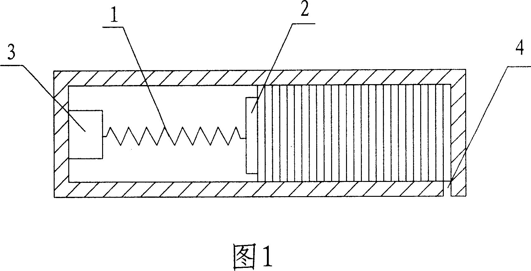
[0010] The first embodiment, as shown in Fig. 1, a card issuing machine according to the present invention includes a card storage box and a reader. The card storage box is cylindrical, placed horizontally on the card dispenser, and the card is in a vertical state in the card storage box. A spring 1 is installed in the card storage box. One end of the spring 1 is equipped with an iron block 2 and placed on the card, and the other end is also equipped with an electromagnet 3. When the electromagnet is energized, the electromagnet attracts the iron block 2 to make the spring 1 Move away from the direction of the card, so the force of the spring 1 on the card is removed, so that the card falls out of the card outlet 4 at the lower part of the card storage box. In addition, one end of the card output channel is connected with the card output port, the other end is connected with the supporting tray, and a reader / writer is installed on one side of the card output channel.

[0011] In o...

Embodiment 2

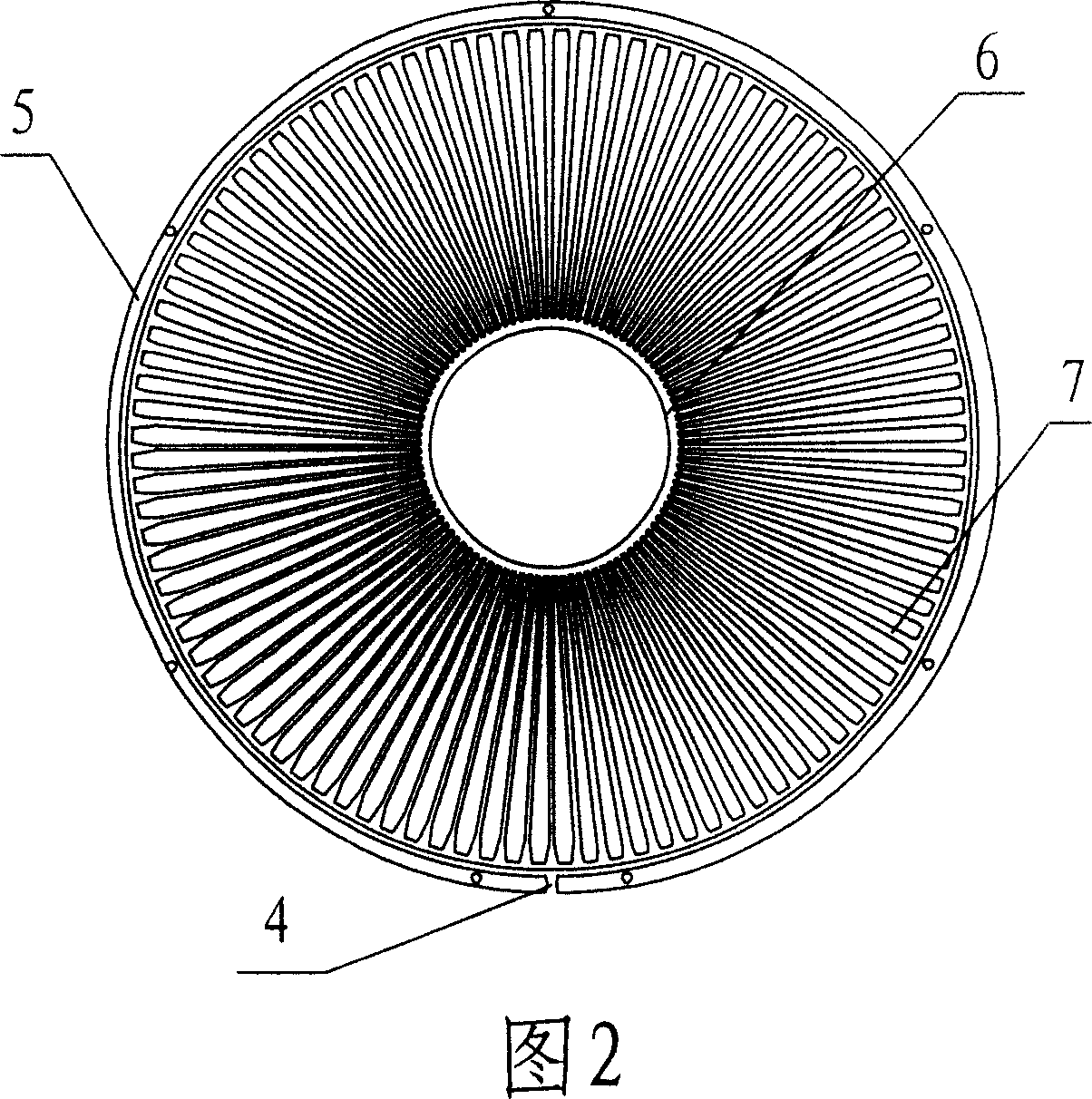
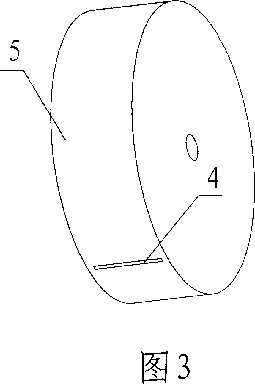
[0012] Second embodiment, as shown in Figure 2, Figure 3, Figure 4, a card issuing machine according to the present invention, the card storage box is a turntable type card storage box, the card storage box includes a cylinder 5, a bayonet outlet 4 is opened on the side wall of the cylinder 5. There is a sleeve 6 inside the cylinder 5. The sleeve 6 is rotatably connected with the cylinder 5, and a plurality of card slots 7 are arranged radially on the sleeve 6, and each slot can Insert a card. The rest is the same as the first embodiment.

Embodiment 3

[0013] The third embodiment, as shown in FIGS. 5 and 6, in the card issuing machine of the present invention, the card storage box is a turntable type card storage box, and the bayonet outlet 4 is opened on the bottom surface of the cylinder 5. The rest is the same as the second embodiment.


PUM


Abstract

A card sending machine, including the card storage box and the reader-writer, the card storage box is on the card sending machine in order to make the cards to be the erect state in it as the due-out state, the card bayonet socket sets at the card storage box downward, one end of the bayonet channel connects with the bayonet socket, the other end connects with the stock, the reader-writer set on one side of the bayonet channel.

Description

Technical field [0001] The invention relates to a card issuing machine used in a highway toll system. Background technique [0002] For the unattended automatic card issuing machine in the highway toll system, the driver only needs to press the button, and the card issuing machine will automatically issue the IC card loaded with the entrance information to the driver, which greatly improves the card issuing efficiency. The existing card issuing machine has a card storage box, a card dial mechanism, a reader and a transmission mechanism. The card storage box is placed vertically in the card issuing machine, and the card storage box has a spring and a card holder. The cards are stacked horizontally in the card storage box, and the spring and the card holder are used to top the top cover of the card storage box. In order to realize the cards are dialed out from the card box one by one. When the card is issued, the card at the top cover of the card box is first dialed out and transmi...

Claims


Application Information

Patent Timeline
Patent Type & Authority Applications(China)
IPC IPC(8): G07B15/00G07B3/00B65D83/08G07B15/06
Inventor 曹烁辰
Owner GUANGDONG ELECTRONICS TECH RES INST
Why Eureka
Try Eureka