Tyre mould

A tire mold and mold technology, applied in the field of molds, can solve the problems of high manufacturing cost, huge vulcanization equipment, large mold quality, etc., and achieve the effects of reducing production cost, simple structure, and improving production efficiency

Inactive Publication Date: 2007-03-28
QINGDAO YUANTONG MACHINERY CO LTD
View PDF0 Cites 16 Cited by
  • Summary
  • Abstract
  • Description
  • Claims
  • Application Information

AI Technical Summary

Problems solved by technology

[0005] The problem to be solved by the present invention is to overcome the shortcomings of existing tire molds such as large mold mass, bulky vulcanization equipment, and high manufacturing cost when the mold is opened and closed for up-and-down reciprocating motion.

Method used


Image

  • Tyre mould
  • Tyre mould
  • Tyre mould

Examples


Embodiment 1

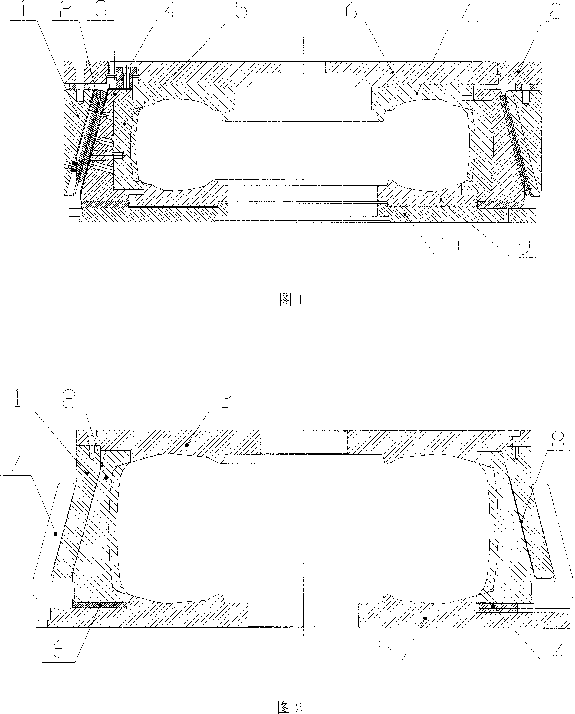
[0030] As shown in Figure 2, 1 is the middle mold cover, 3 is the upper side plate, 4 is the slider, 5 is the lower side plate, 6 is the anti-friction block, 2 is the pattern block, which are located on the upper side plate 3, the lower side plate 5 to form a tire crown pattern, pattern blocks 2 are evenly distributed on the same circumference, and a slide block 4 is fixed at the bottom thereof. The inclined surface of the outer surface of the pattern block 2 and the inclined surface of the inner surface of the middle mold sleeve 1 are relatively matched and slid, and the pattern block 2 and the lower side plate 5 are positioned and connected in the axial direction of the mold, and there is no axial displacement between them. 1. During the mold closing process, each pattern block can simultaneously reciprocate synchronously on the upper part of the lower side plate 5 along the radial direction of the mold. Plate 3 moves up and down. A plurality of pattern blocks 2 are folded ...

Embodiment 2

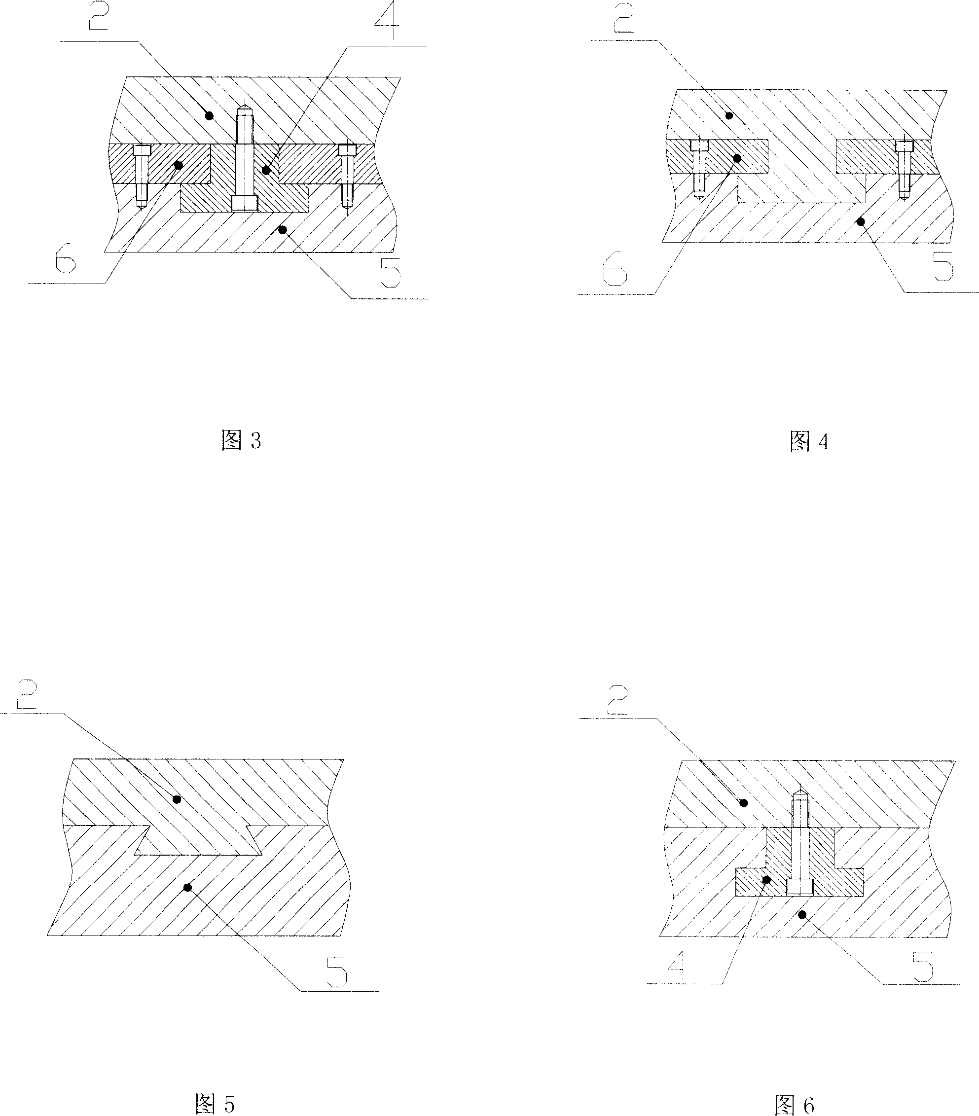
[0036] The connection mode between the pattern block 2 and the lower side plate 5 in the axial direction of the mold is shown in Figure 4. The protrusion at the bottom of the pattern block 2 is integrated with the pattern block 2. The section of the protrusion is an inverted "T" shape, and the lower side plate The inverted "T"-shaped groove on the upper part of 5 is formed by the groove on the upper part of the lower side plate 5 and two friction-reducing blocks 6 fixedly installed along the radial edge of the groove.

[0037] Others are the same as embodiment 1.

Embodiment 3

[0039] The connection mode between the pattern block 2 and the lower side plate 5 in the axial direction of the mold is shown in Figure 5. The protrusion at the bottom of the pattern block 2 is integrated with the pattern block 2, and the section of the protrusion is dovetail-shaped. The upper part of the lower side plate 5 The groove is also correspondingly a dovetail groove.

[0040] Others are the same as embodiment 1.


PUM


Abstract

The present invention relates to a vulcanized radial tire mould. It includes the following several portions: upper side plate, middle mould cover, lower side plate and tread block positioned between upper side plate and lower side plate for forming tire tread face. Said the mould is simple, can greatly reduce tire cost.

Description

technical field [0001] The invention relates to molds, in particular to a mold for vulcanizing radial tires. Background technique [0002] As shown in Fig. 1 of the existing tire mold, a plurality of tile-shaped pattern blocks 5 are evenly distributed on the same circumference, and form a circumferentially closed pattern circle after being closed. The pattern blocks 5 are fixed on the bow seat 3 in one-to-one correspondence; the outer surface of the bow seat 3 is a conical surface or an inclined plane, and the inner surface of the middle mold cover 1 and the outer surface of the bow seat 3 cooperate and slide relative to each other. Each conical surface or inclined plane on the outside of the bow-shaped seat 3 is vertically fixed with a "T"-shaped guide strip 2, and each "T"-shaped guide strip is in the corresponding "T"-shaped groove on the inner surface of the middle die sleeve 1 slide. The slide block 4 fixed on the top of the arc seat 3 is positioned and connected with...

Claims


Application Information

Patent Timeline
Patent Type & Authority Applications(China)
IPC IPC(8): B29C33/20B29C33/30B29C33/42B29L30/00
Inventor 宁新华
Owner QINGDAO YUANTONG MACHINERY CO LTD
Why Eureka
Try Eureka