Engine correct-timing drive system mounting method and positioning tool

A drive system and installation method technology, applied in the direction of engine components, machines/engines, manufacturing tools, etc., can solve the problems of undiscovered installation methods and positioning tools, etc., and achieve the effect of simple tooling tools, accurate positioning, and easy operation

Inactive Publication Date: 2007-03-28
CHERY AUTOMOBILE CO LTD
View PDF0 Cites 14 Cited by
  • Summary
  • Abstract
  • Description
  • Claims
  • Application Information

AI Technical Summary

Problems solved by technology

No public installation method and positioning tool for

Method used


Image

  • Engine correct-timing drive system mounting method and positioning tool

Examples


Embodiment Construction

[0016] Embodiment of the installation method of the engine timing drive system:

[0017] (1) Rotate the crankshaft to a crankshaft angle of 270°, and then manually insert the crankshaft positioning pin (the positioning pin must match the crankshaft hole well);

[0018] (2) Put the timing gear on the crankshaft, tighten it to 130Nm with a 130Nm torque wrench, and then turn it clockwise for 65 degrees;

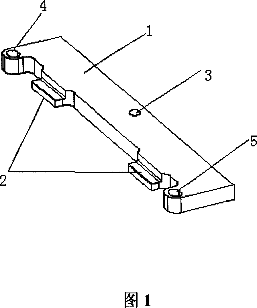
[0019] (3) Rotate the camshaft to a suitable position to insert the camshaft positioning tool (this positioning tool must match the slot on the camshaft perfectly). Use 3 pieces of M6x20 (5 +5 The tightening torque of Nm) bolts to fix the camshaft alignment tool;

[0020] (4) Put the camshaft timing gear on, insert the M12 bolt into the center screw hole of the timing gear and tighten it to 3Nm with a tool (make sure that the camshaft gear cannot shake after being fastened by the bolt);

[0021] (5) Install the tensioning wheel, and the fixing hook on the tensioning wheel mus...


PUM


Abstract

This invention relates to an installation method for timing drive system of engines including: 1, setting phase of a crank by a crank location pin to mount a timing gear, 2, rotating two camshafts to the required phase and bolting a locating tool on a cap end and mounting the camshaft timing gear without screw down, 3, mounting a tension wheel and a timing belt and adjusting the adjuster of the wheel and screwing down the timing gear, 4, removing the locating tool and the pin, 5, calibrating position of the tension wheel. Two clamp blocks are set corresponding to the grooved position of the dual-camshaft on the long edge of a ruler body and more than two fixed screw holes are set on the body to form a locating tool of the invented method.

Description

technical field [0001] The invention relates to an installation method and a positioning tool for an engine timing drive system, in particular to an installation method and a positioning tool for a double overhead camshaft (DOHC) engine timing drive system. Background technique [0002] At present, various engines and manufacturers have different plans on how to align the phase relationship between the camshaft and the crankshaft when the timing system is installed. Correctly aligning the phase relationship between the camshaft and the crankshaft is related to the stable working condition and performance of the engine. There is no known installation method and positioning tool for the timing drive system of a double overhead camshaft (DOHC) engine. Contents of the invention [0003] In order to solve the technical problem of how to align the phase relationship between the camshaft and the crankshaft when the timing system is installed, the present invention provides an en...

Claims


Application Information

Patent Timeline
IPC IPC(8): F01L1/348B23P19/04
Inventor 刘世文刘杨
Owner CHERY AUTOMOBILE CO LTD
Why Eureka
Try Eureka