Noise removing circuit

A noise suppression and circuit technology, applied to electrical components, transmission systems, etc., can solve problems such as audio signal error interpolation, and achieve the effect of suppressing impulse noise

Inactive Publication Date: 2007-03-28
SANYO ELECTRIC CO LTD
View PDF1 Cites 3 Cited by
  • Summary
  • Abstract
  • Description
  • Claims
  • Application Information

AI Technical Summary

Problems solved by technology

In the case where the noise suppression circuit performs an interpolation process based on the detection of impulse noise using linear prediction, even when an audio signal is actually generated, the generation period of the audio signal may be erroneously interpolated as impulse noise

Method used


Image

  • Noise removing circuit
  • Noise removing circuit
  • Noise removing circuit

Examples


Embodiment Construction

[0023] At least the following details will become apparent from the contents of the specification and drawings.

[0024] Regarding the case of applying the noise suppression circuit of the present invention to an AM receiver, the following embodiments of the present invention will be described.

[0025] == Structure of AM Receiver ==

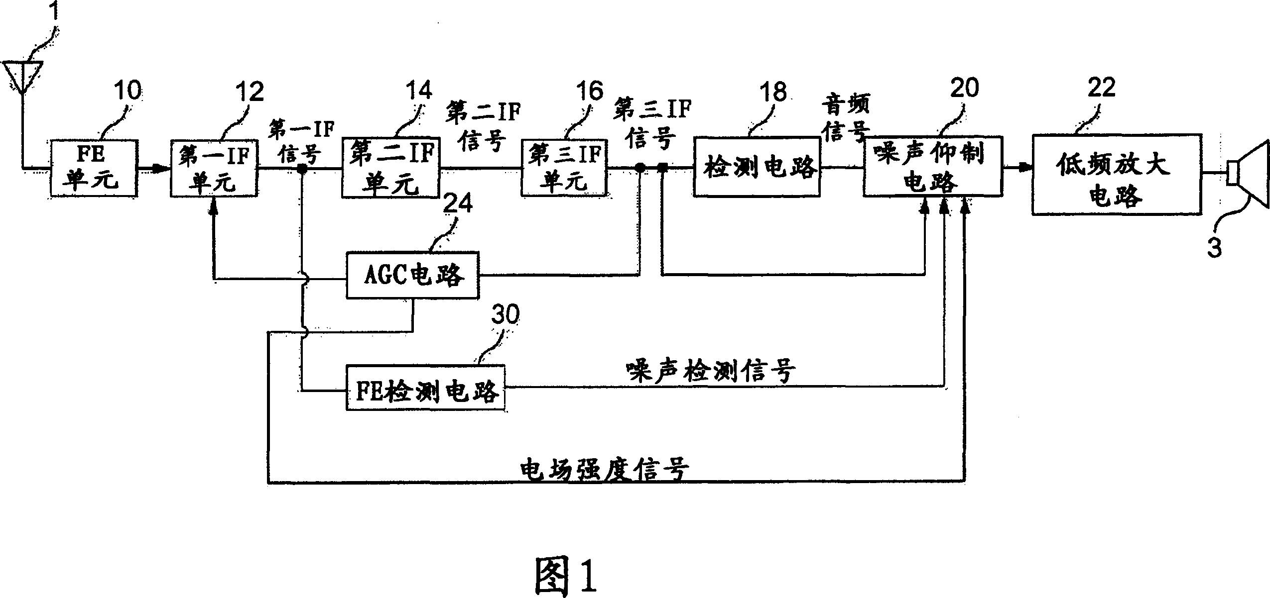
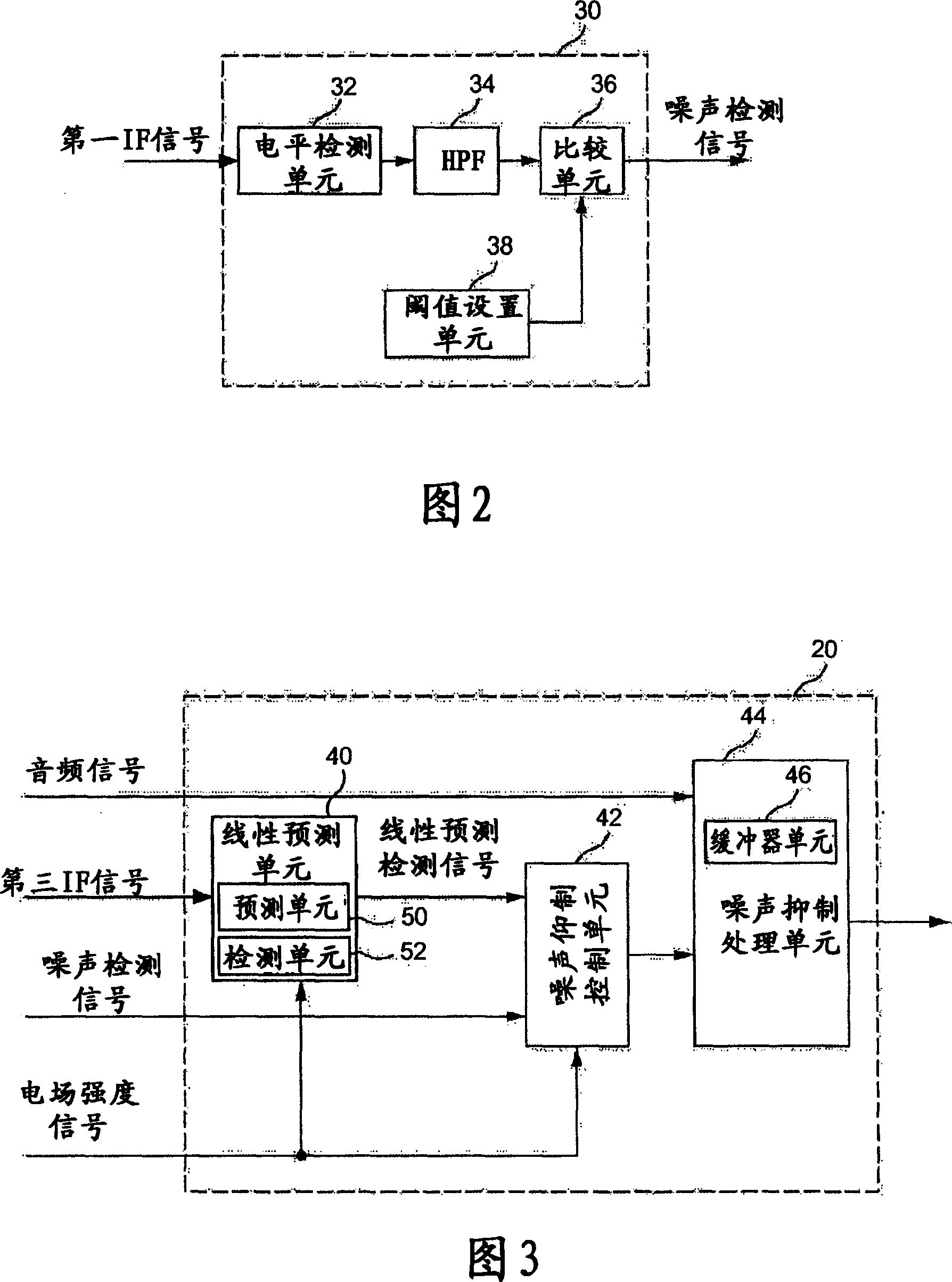
[0026] Fig. 1 is a block diagram showing a structural example of an AM receiver using the noise suppressing circuit of the present invention. The AM receiver shown in Figure 1 includes a front end (hereinafter referred to as FE) unit 10, a first intermediate frequency (hereinafter referred to as IF) unit 12, a second IF unit 14, a third IF unit 16, a detection circuit 18, a noise suppression circuit 20 , low frequency amplifier circuit 22 , AGC circuit 24 and FE detection circuit 30 .

[0027] The FE unit 10 amplifies a signal received by the antenna 1 to form a signal of a level required by the first IF unit 12 of the next stage. Amplificati...


PUM


Abstract

The invention provides a noise removing circuit having an improved pulse noise detection accuracy irrespective of the intensity of the electric field by selecting a noise detection signal according to the intensity of the electric field. A noise removing circuit comprising a predicting section for predicting the value of an intermediate frequency signal at a predetermined time on the basis of the intermediate frequency signal previously generated before the predetermined time, a detecting section for comparing the difference in magnitude between the predicted value of the intermediate frequency signal at the predetermined time and the value of the previously generated intermediate frequency signal with a predetermined threshold and thereby outputting a second detection signal representing the occurrence of the pulse noise, and a noise removal control unit for selectively outputting to a noise removing unit either a first detection signal representing the occurrence of pulse noise generated by level-detecting the intermediate frequency signal of the received signal or the second detection signal as a signal for interpolating the period when the pulse noise occurs according to the electric field intensity signal generated from the intermediate frequency signal.

Description

[0001] Cross References to Related Applications [0002] This application claims priority from International Patent Application PCT / JP2005 / 002897 filed February 23, 2005, the entire contents of which are hereby incorporated by reference. technical field [0003] The present invention relates to noise suppression circuits. Background technique [0004] When receiving radio broadcasts, for example, when receiving AM broadcasts with a vehicle-mounted AM receiver, the received signal may be mixed with noise in the form of pulses with a short time width and high amplitude (hereinafter referred to as pulse noise), such as electronic rearview mirrors of vehicles Or ignition noise from wiper effect. Impulse noise output from the receiver is aurally undesirable. [0005] Therefore, the noise suppression circuit interpolates the generation period of such impulse noise in order to suppress the impulse noise from the audio signal collected by AM detection. The interpolation method in...

Claims


Application Information

Patent Timeline
Patent Type & Authority Applications(China)
IPC IPC(8): H04B1/10
CPCH04B1/1036H04B1/10
Inventor 斋藤康二平社丰平正明
Owner SANYO ELECTRIC CO LTD
Why Eureka
Try Eureka