Horizontal disk injecting forming unit

An injection molding machine and disc technology, which is applied in the field of disc plastic injection molding machines, can solve the problems of shortening the mold clamping cylinder piston, reducing the service life of the disc, and low production efficiency, so as to shorten the time spent and the stroke distance, and the effect of increasing productivity

Inactive Publication Date: 2007-04-04
金孝禹
View PDF1 Cites 8 Cited by
  • Summary
  • Abstract
  • Description
  • Claims
  • Application Information

AI Technical Summary

Problems solved by technology

[0006] The disadvantage of the traditional disc horizontal plastic injection molding machine is: since the mold clamping cylinder is set under the disc, in order to complete the mold clamping and delay pressure maintenance work, the piston of the mold clamping cylinder must move from the bottom to the top of the mold clamping plate. The hole is pushed out and higher than the disc until the mold is pressed against the injection head, but in order not to affect the normal rotation of the disc, the distance between the piston of the clamping cylinder and the injection head above the disc is relatively long. That is, the stroke of the mold clamping cylinder piston is relatively long, so it takes a long time for this type of injection molding machine to complete an injection molding work, and the production efficiency is low
[0009] This type of injection molding machine can shorten the stroke distance and time spent on the mold clamping cylinder piston during the mold clamping process, but when this type of injection molding machine is injected, the melted plastic fluid is directly discharged from the mold through the nozzle of the injection molded part. The side of the injection mold is injected into the cavity of the mold. This injection method requires very precise positioning of the feed hole of the mold; it has accurate positional relationships such as the height and size of the feed holes of each pair of molds positioned on the disc. Requirements, but because the soles are divided into sizes, high heels and flat heels, the size and height of the shoe molds used are also different, but it must be satisfied so that the height of all positioning holes must be consistent with the nozzle of the injection molded parts used. The requirement of maintaining the same height will make the adaptability of this type of injection molding machine smaller, for example, it cannot adapt to processing higher and lower molds, or larger and smaller molds at the same time, and it also improves manufacturing. The difficulty of the sole mold of this injection molding machine
[0010] In addition, because this kind of injection molding machine is in the working process of mold clamping and delayed pressure holding, the piston of the mold clamping cylinder is directly pressed against the mold, and the mold is supported by the disk with the edge hanging in the air, that is, the disk is placed in the mold when it is set. The edge must bear all the pressure of the piston of the mold clamping cylinder. Due to the frequent and huge pressure, the edge of the disc will be deformed under pressure for a long time, making the resistance of the disc too large when it rotates or it can no longer continue to work normally, reducing the pressure. The service life of the disc

Method used


Image

  • Horizontal disk injecting forming unit
  • Horizontal disk injecting forming unit
  • Horizontal disk injecting forming unit

Examples


Embodiment 1

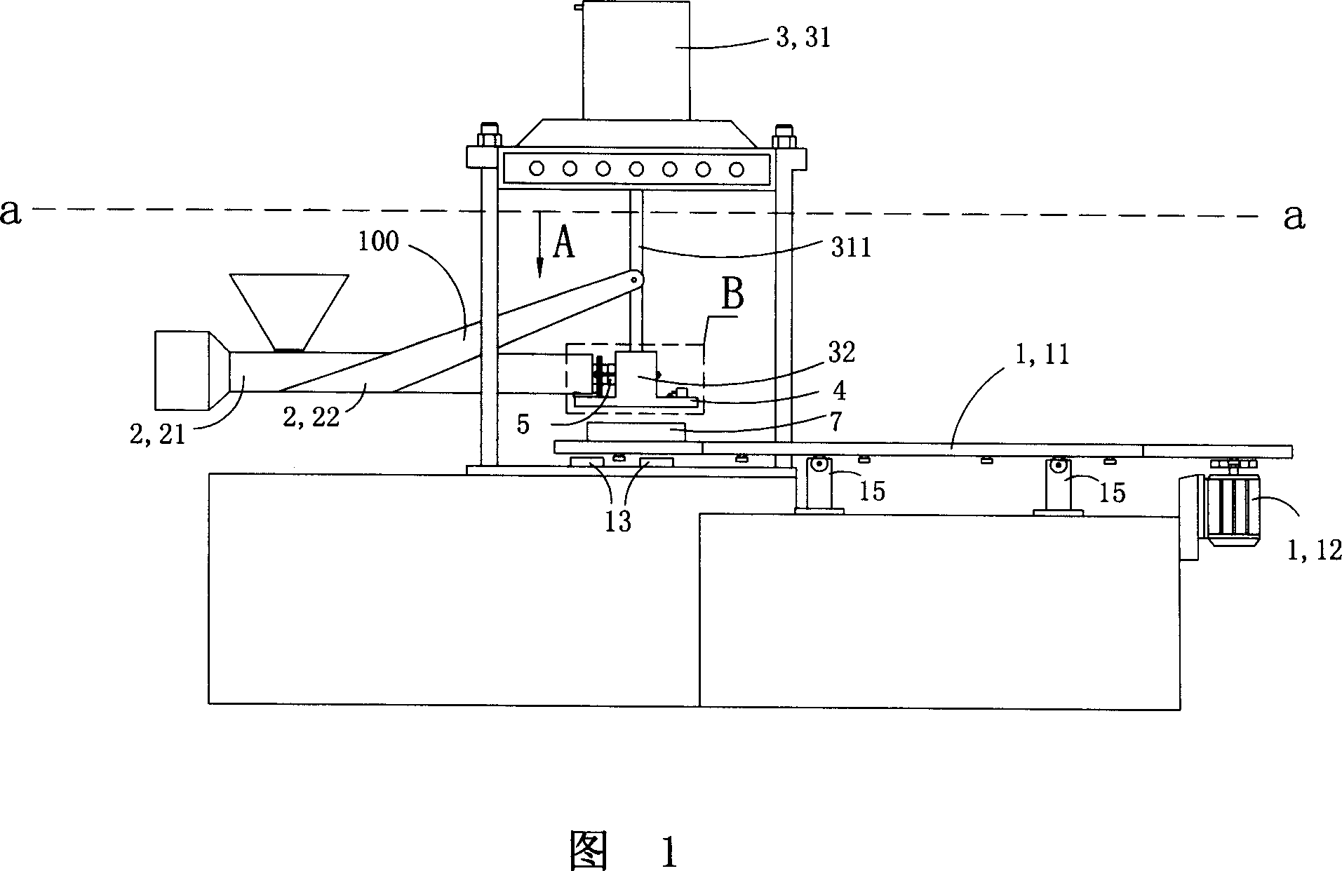
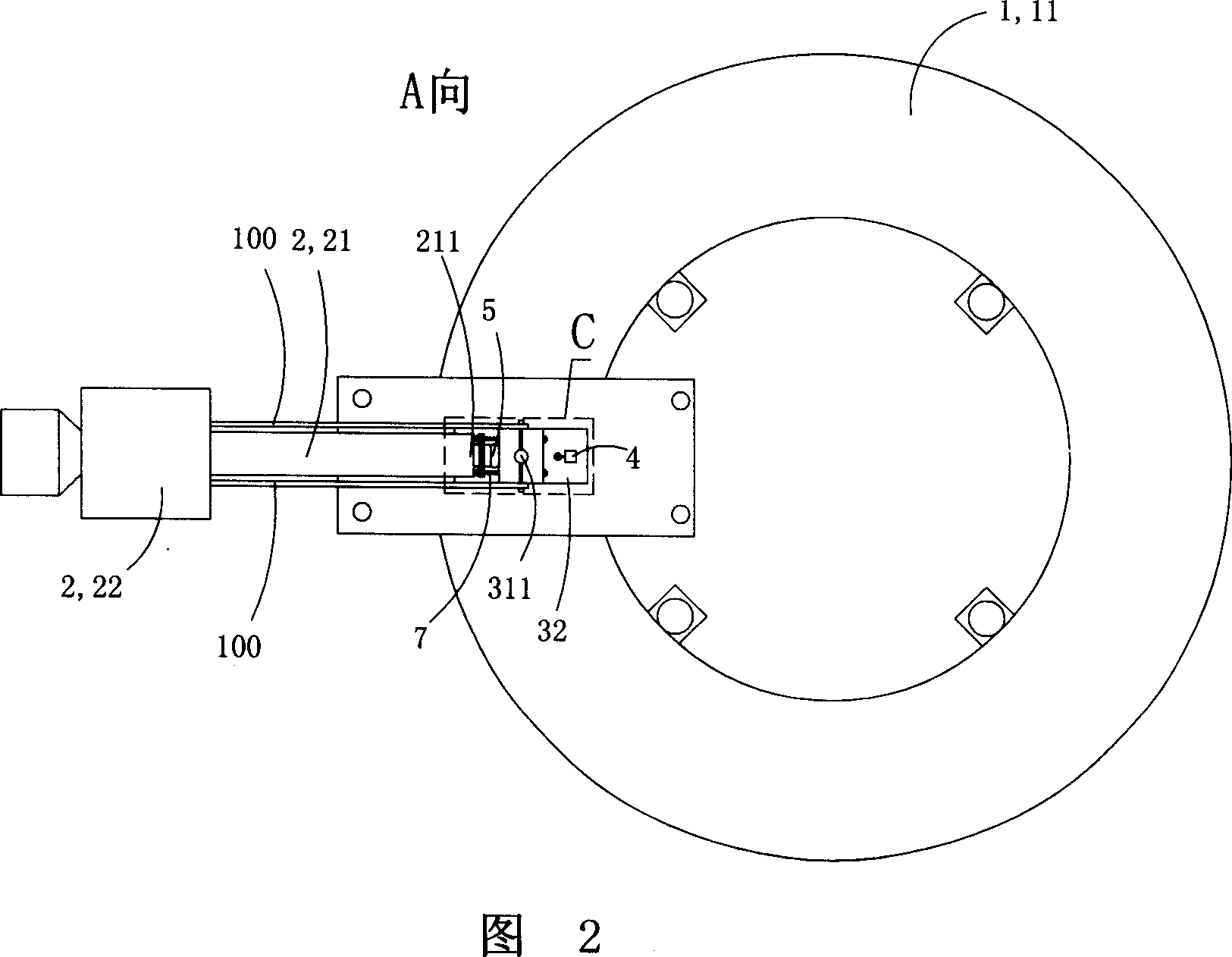
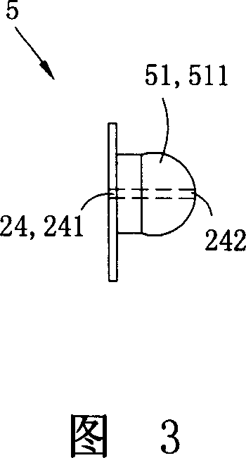
[0053] 1 to 7, the disc horizontal plastic injection molding machine of this embodiment has a turntable device 1, an injection device 2 for injecting plastic fluid into the mold, and a mold clamping device 3; the turntable device 1 includes a rotatable disc 11. The motor 12 and four fixed feet 15 that drive the rotation of the disk 11; the injection molding device 2 includes a horizontal injection molding part 21 and an injection coupling 5, and the injection coupling 5 is provided with an injection material channel 24; the mold clamping device 3 includes a mold clamping cylinder 31 and an injection head 32 arranged above the disc 11; the mold clamping cylinder piston 311 can move up and down, and the mold clamping device 3 also includes the injection The head 32 is fixedly arranged on the lower end of the piston 311 of the clamping cylinder, and can move up and down as the piston 311 moves up and down; The feed port 331 is arranged on the side of the injection head 32, and th...

Embodiment 2

[0065] See Fig. 8 to Fig. 9, this embodiment is basically the same as Embodiment 1, the difference is that: the turntable device 1 also has a pressure-bearing tray 13 fixedly arranged relative to the mold clamping cylinder 31, two for bearing Support the elastic standoff 14 of described disc 11 and two fixed standoffs 15; The disc 11 is held up and is 2 mm to 5 mm higher than the upper surface of the pressure-bearing tray 13. When the disc 11 is pressed downward by the piston 311 of the clamping cylinder, the disc 11 and the elastic stand 14 is pressed to lower its height, so that the pressure-bearing tray 13 holds up the disc 11 .

[0066] Since the turntable device 1 of this embodiment also has a pressure-bearing tray 13 fixedly arranged relative to the clamping cylinder 31 and two elastic legs 14 for supporting the disc 11; When the disc 11 is not pressed downward by the piston 311 of the clamping cylinder, the elastic standoff 14 lifts the disc 11 and is 2 mm to 5 mm high...

Embodiment 3

[0068] See Figure 10 to Figure 15, this embodiment is basically the same as Embodiment 2, the difference is that: the left end of the injection coupling 5 is fixedly connected with the injection molding part 21, and the injection coupling 5 The right side end of the injection head 32 is movably connected, and the injection molding part 21 is also movably connected with the base 22 of the injection molding device; the injection molding part 21 can be It moves back and forth in the horizontal direction and can rotate a certain angle in the vertical direction.

[0069] The injection head 32 has two special-shaped connecting holes 35, and the special-shaped connecting hole 35 is composed of a limiting hole 351 for setting bolts and a vertically large outer and inner small hole 351 and a fixing hole for setting nuts. 352; the end of the special-shaped coupling hole 35 close to the injection coupling 5 is the limiting hole 351, and the end away from the injection coupling 5 is the l...


PUM


Abstract

A horizontal disc type injection moulding machine is composed of a rotary disc unit, a injection moulding unit and a mould closing unit. Said injection moulding unit consists of a horizontal injection part and an injection jointer for allowing the fused plastic fluid to flow through it. Said mould closing unit comprises and mould closing cylinder with piston moving up and down, and an injection head fixed to the lower end of said piston for injecting the fused plastic fluid into moulding cavity of mould.

Description

technical field [0001] The invention belongs to a plastic injection molding machine, in particular to a disc type plastic injection molding machine. Background technique [0002] Disc-type plastic injection molding machine is a kind of equipment specially used for manufacturing shoe soles. The disc used is often equipped with multiple sole molds of the same style and different sizes at the same time. Therefore, it is necessary to set the molds on the turntable for plastic injection molding. The machine injects molds with different styles and codes in stages, and facilitates the mold opening and taking out the molded soles and other processes. [0003] The disc-type plastic injection molding machine mainly includes a turntable device, an injection device for injecting plastic fluid into the mold, and a mold clamping device. The turntable device includes a rotatable disc and a disc drive device for controlling the rotation of the disc. The injection device Includes injection ...

Claims


Application Information

Patent Timeline
Patent Type & Authority Applications(China)
IPC IPC(8): B29C45/06B29C45/27B29C45/20B29C45/17B29C45/23
Inventor 金孝禹
Owner 金孝禹
Why Eureka
Try Eureka