Speed reducer, production method for speed reducer, roller bearing, and production method for crank shaft
A technology of reducer and crankshaft, which is applied in the directions of crankshaft, bearing components, shaft and bearing, etc., can solve the problems such as the limitation of small diameter of differential swing reducer and the unavoidable enlargement of crankshaft bearing.
- Summary
- Abstract
- Description
- Claims
- Application Information
AI Technical Summary
Problems solved by technology
Method used
Image

Examples
no. 1 approach
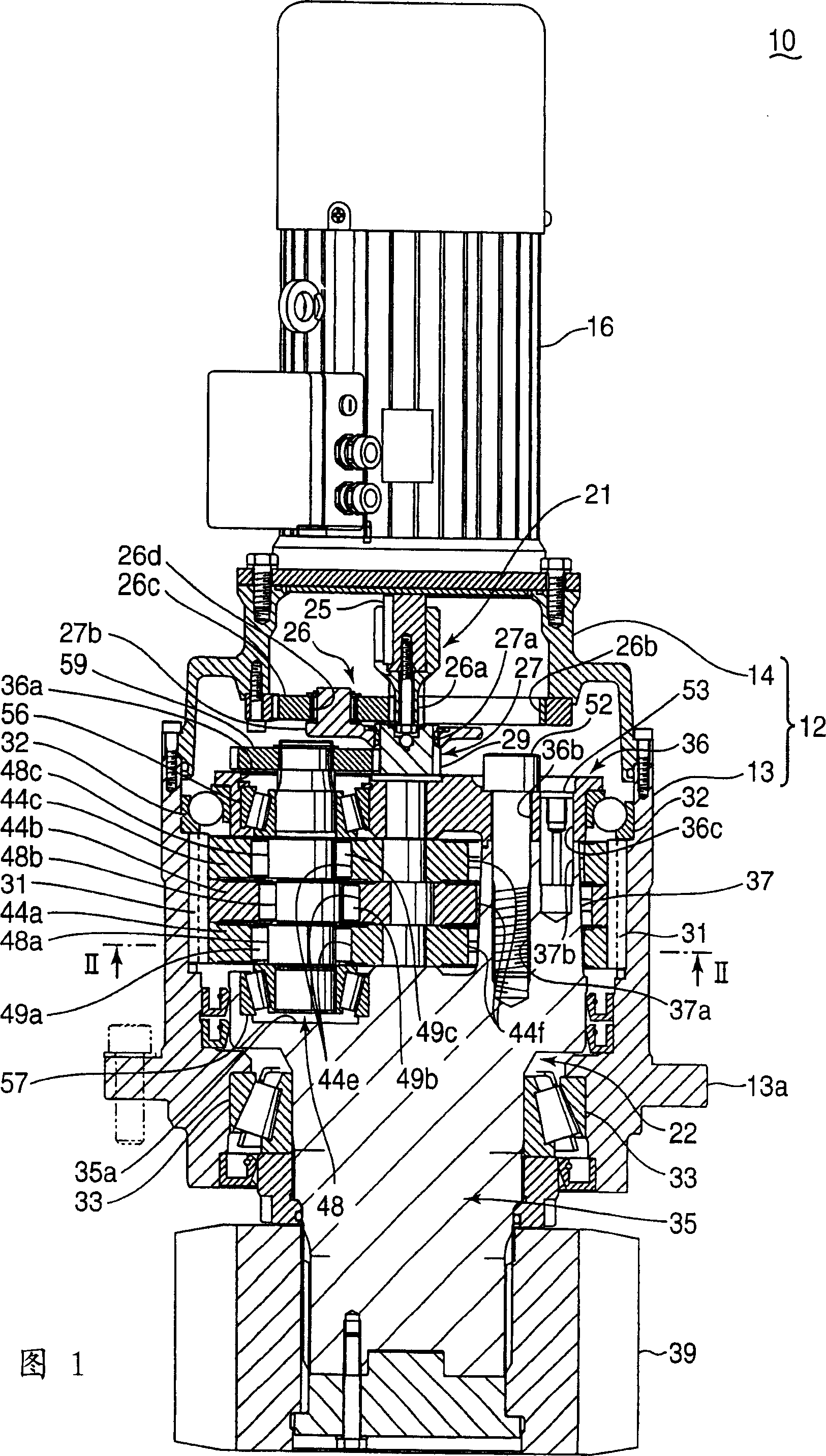
[0067] The differential swing speed reducer (hereinafter simply referred to as speed reducer) 10 in the first embodiment is, for example, a speed reducer that can be used as a pitch conversion device of wind power generation equipment, and can also be used for robots. Speed reducers, speed reducers for construction machinery, etc. for driving or turning, etc. The speed reducer 10 has an outer housing 12 . The outer casing 12 is formed by connecting a cylindrical portion 13 formed in a cylindrical shape and a cover portion 14 formed in a bottomed cylindrical shape. The cylindrical part 13 is provided with a flange part 13a for attaching to, for example, a fixing frame (not shown) of a power generator. The cylindrical part 13 is coupled with the fixing frame through the flange part 13a. A driving motor 16 as a driving part is fixed to the cover part 14 .
[0068] The speed reducer 10 has an input shaft 21 and a bracket 22 as an example of an output shaft portion. The drive...
no. 2 approach
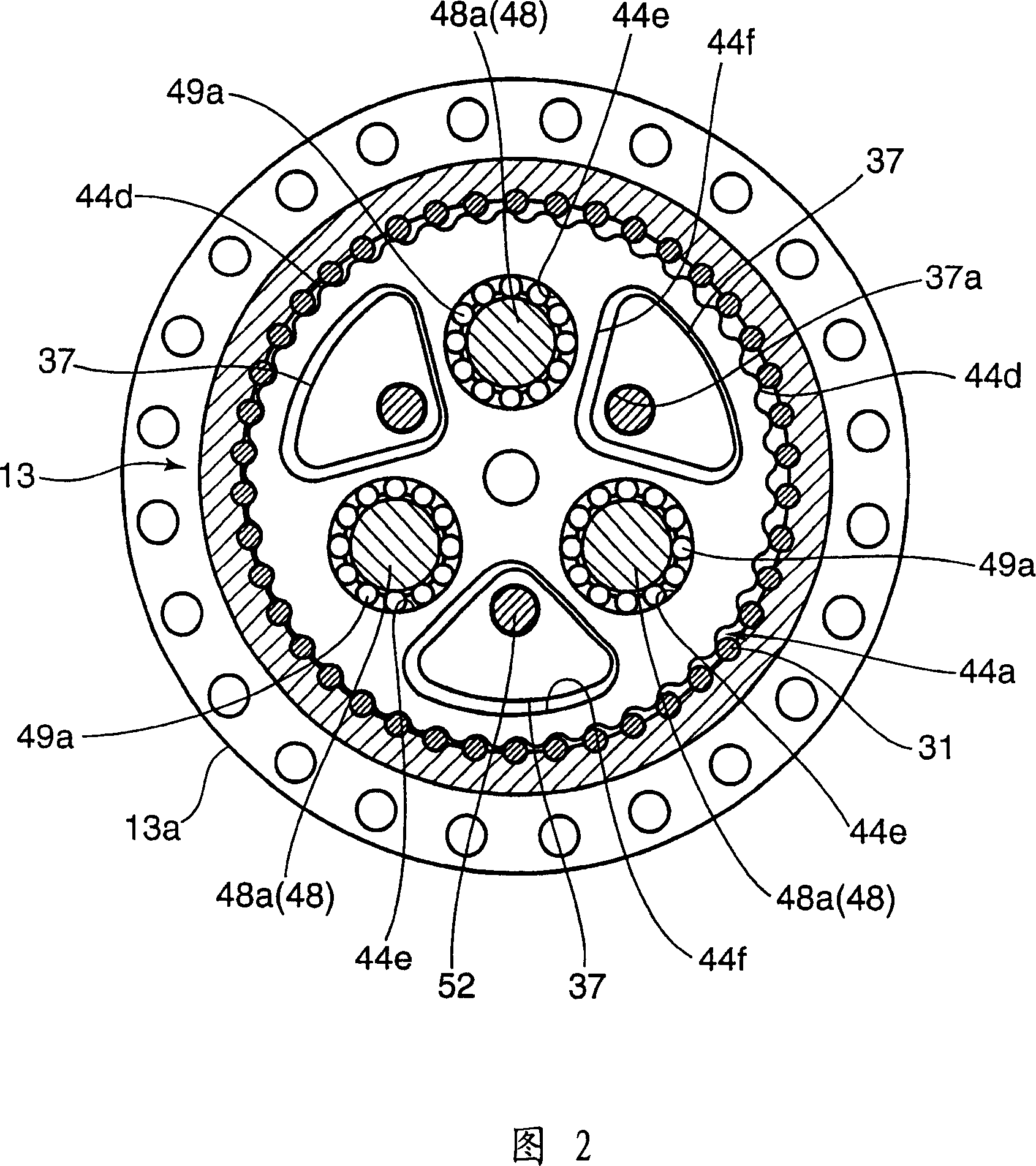
[0098] In the speed reducer 10 according to the second embodiment, the first to third eccentric portions 48 a to 48 c of the crankshaft 48 are formed into cylindrical shapes eccentric with respect to the axis of the crankshaft 48 by the eccentricity e, respectively. Further, the first to third eccentric portions 48a to 48c are arranged so as to have a phase difference of an angle θ (about 120° in the second embodiment) and have substantially the same outer diameter d (see FIG. 15 ).
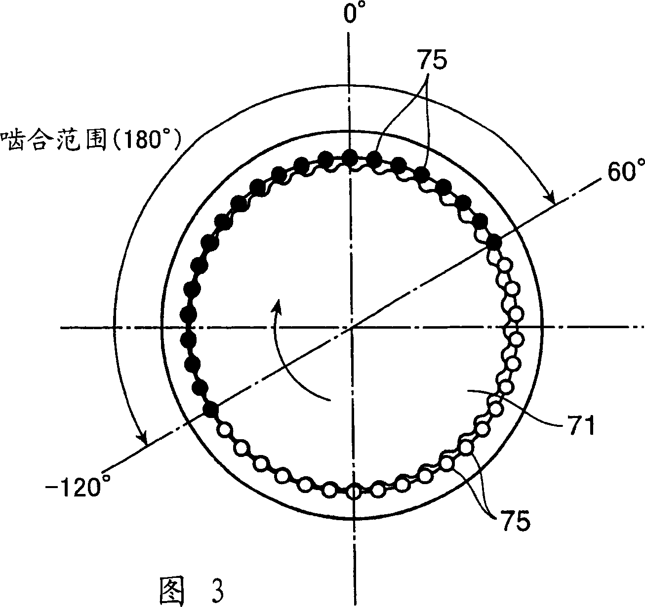
[0099] Also, the speed reducer 10 according to the second embodiment has improvements in the parts of the first to third bearings 49a to 49c. Specifically, as shown in FIGS. 11 to 15 , the first to third bearings 49 a to 49 c are constituted by a plurality of (12 in the second embodiment) cylindrical rollers 50 and retainers 51 , respectively.
[0100] The retainers 51 of the first to third bearings 49 a to 49 c hold the respective rollers 50 at predetermined intervals around the first to third e...
no. 3 approach
[0116]The speed reducer according to the third embodiment is the same differential swing type speed reducer as the speed reducer 10 of the second embodiment shown in FIG. 11 . Only the speed reducer of the third embodiment uses the first to third roller bearings 149a to 149c in place of the first to third bearings 49a to 49c of the second embodiment described above.
[0117] Specifically, in the speed reducer according to the third embodiment, the first to third eccentric portions 48a to 48c (shaft members) of the crankshaft 48 are respectively inserted into the circular shapes provided on the first to third externally toothed gears 44a to 44c. The state inside the first through hole 44e is supported by the first to third roller bearings 149a to 149c shown in FIGS. 16 to 18 , respectively.
[0118] The first to third roller bearings 149a to 149c have the same structure, respectively, and are constituted by 15 rollers 150 and cages 151, respectively. The rollers 150 are arrang...
PUM
 Abstract
Description
Claims
Application Information
 - R&D
- Intellectual Property
- Life Sciences
- Materials
- Tech Scout
- Unparalleled Data Quality
- Higher Quality Content
- 60% Fewer Hallucinations
Browse by: Latest US Patents, China's latest patents, Technical Efficacy Thesaurus, Application Domain, Technology Topic, Popular Technical Reports.
© 2025 PatSnap. All rights reserved.Legal|Privacy policy|Modern Slavery Act Transparency Statement|Sitemap|About US| Contact US: help@patsnap.com