Surface shape measurement apparatus and method

A device, a technology of a specific shape, applied in the direction of measuring devices, instruments, optical devices, etc., which can solve problems such as beam non-planarity

Inactive Publication Date: 2007-04-04
QINETIQ LTD
View PDF5 Cites 8 Cited by
  • Summary
  • Abstract
  • Description
  • Claims
  • Application Information

AI Technical Summary

Problems solved by technology

However, in most cases (eg US6344898) the wavefront of the resulting beam is clearly non-planar

Method used


Image

  • Surface shape measurement apparatus and method
  • Surface shape measurement apparatus and method
  • Surface shape measurement apparatus and method

Examples


Embodiment Construction

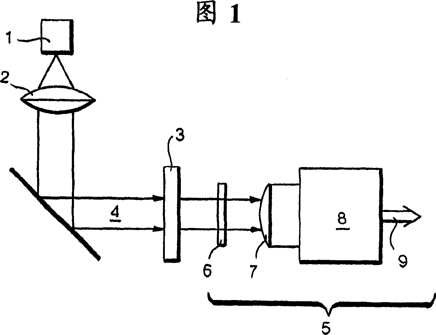
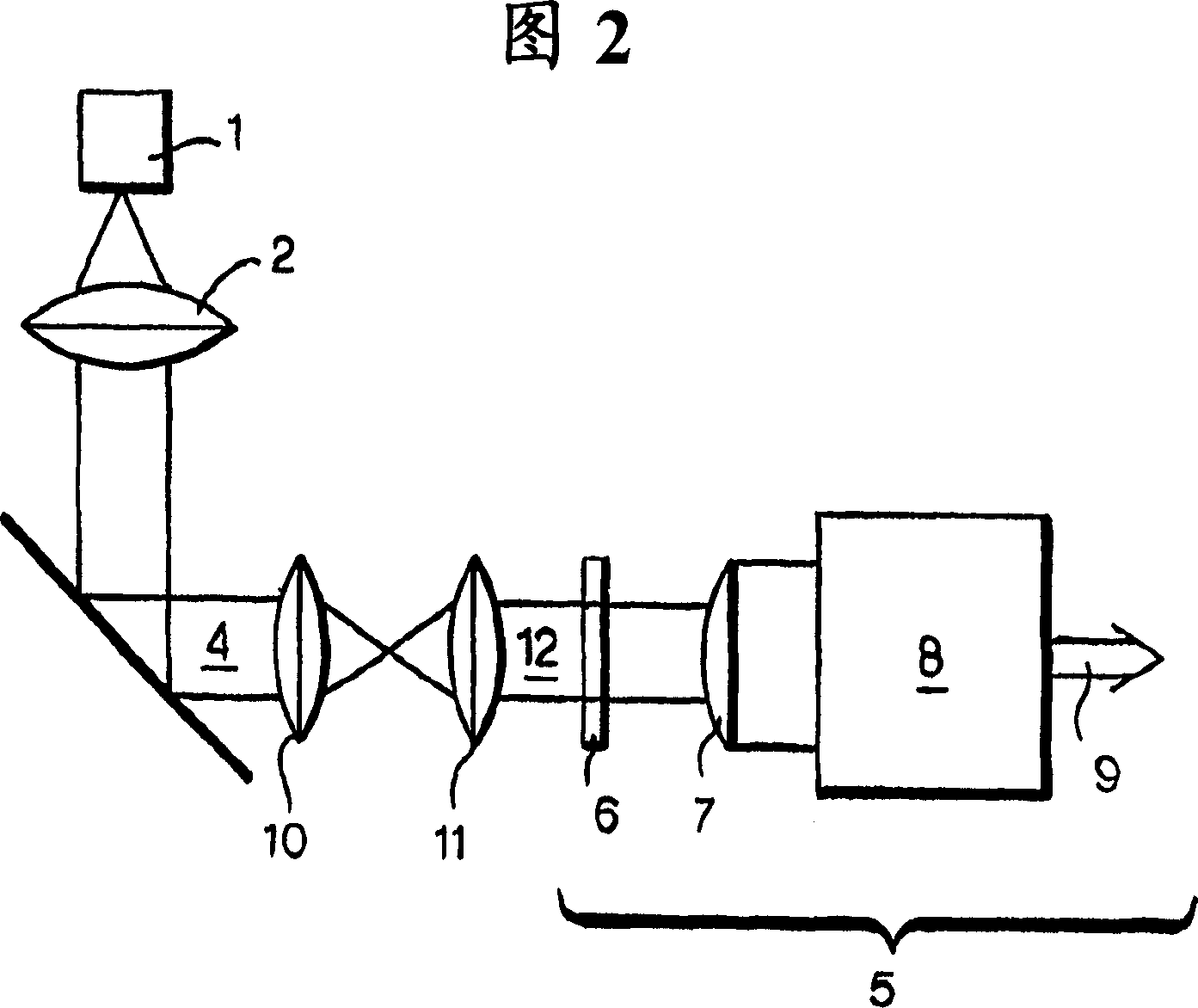
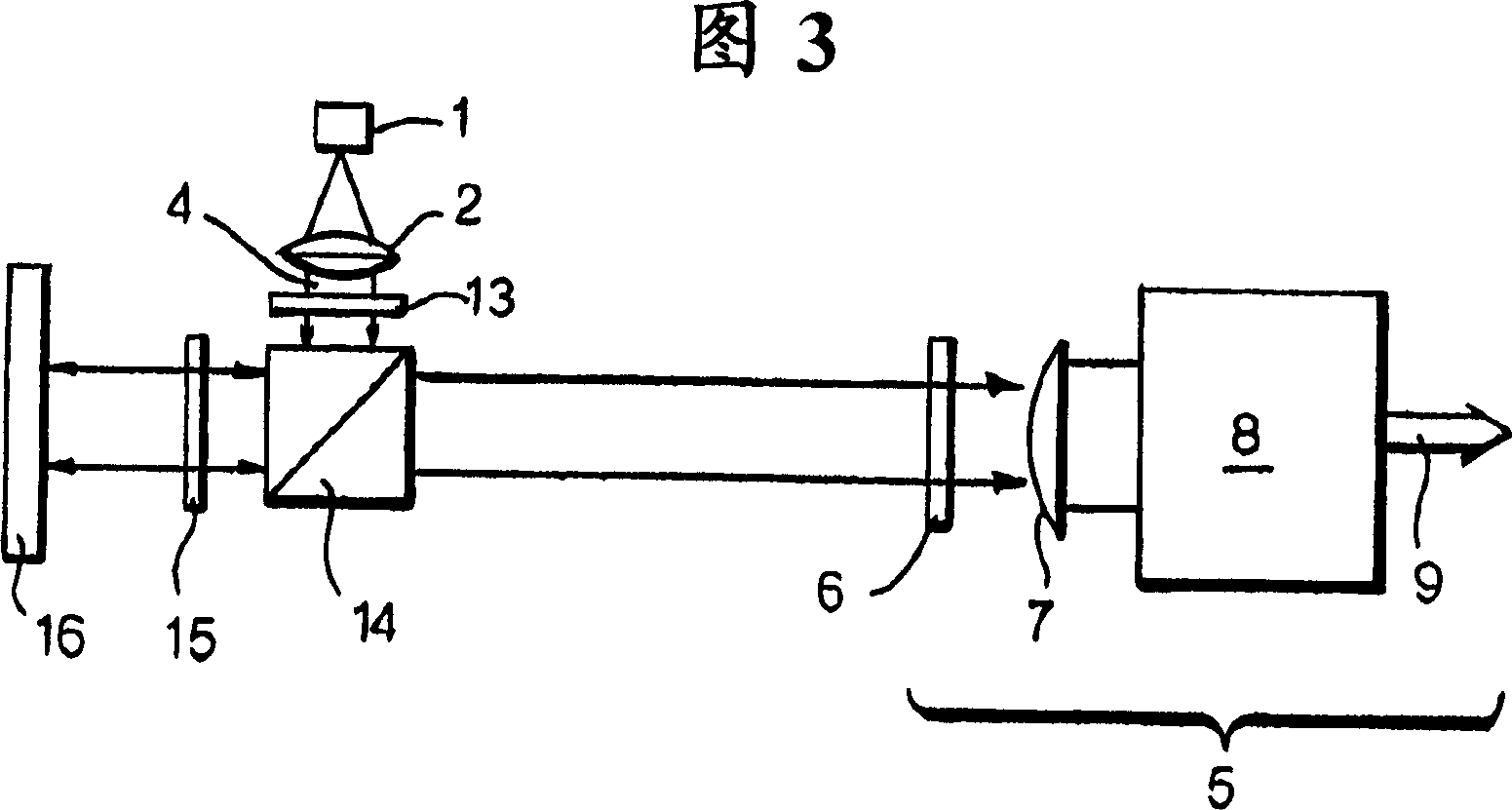
[0044] Each of the embodiments of Figures 1 to 7 includes a wavefront inspection unit 5, which may be as described in our co-pending International Patent Application No. PCT / GB03 / 00964 or our co-pending International Patent Application No. WO04 / 068090 The form of the wavefront sensor described in . However, where it is specifically shown in general terms, the inspection unit 5 is of the form described in our co-pending International Patent Application No. PCT / GB03 / 00979 and contains (in particular) a rectangular deformed grating 6, as As outlined in the aforementioned application, the rectangular anamorphic grating 6 is used to direct the light transmitted through the sheet 3 onto the lens 7 of a CCD camera 8 to provide an output signal 9 for further processing. Ideally, the beam 4 impinges on the sheet 3 at normal incidence.

[0045] As described in the aforementioned application, this combination of elements produces laterally displaced spots at the pixel value imaging phot...


PUM


Abstract

Apparatus for indicating the departure of a shape of an object (3; 11; 16; 18; 22; 26) from a specified shape is described. The apparatus comprises radiation means for directing an incident beam of radiation (4) onto the object, and inspecting means (5) for inspecting the final beam after transmission by or reflection from said object. The apparatus is arranged so that the final beam will have a substantially planar wavefront when said object has said specified shape, and said inspecting means (5) is arranged to determine any departure of the wavefront of the final beam from planarity. In one embodiment, the inspecting means comprises beamsplitting means, for example a diffraction grating (6) or hologram, and detector means such as a CCD camera (8). The beamsplitting means is then arranged to split the final beam into two or more beams and to direct said two or more beams to laterally displaced locations on the detector means.

Description

technical field [0001] The present invention relates to devices and methods for determining the deviation of a shape associated with an object from a specific shape. Background technique [0002] International Patent Application No. WO99 / 46768 (Minister of Defense) describes an imaging system comprising a diffractive grating which is substantially deformed according to a quadratic function to cause an image to be formed under varying focusing conditions. [0003] Our co-pending International Patent Application No. WO03 / 074985 describes a measurement device (and related method) for determining data relating to the local shape (or distribution of local phases) of radiation wavefronts reaching the pupil plane and claims the right therein, wherein said shape is defined by a set of predetermined orthogonal functions, each function is provided with weight coefficients for determining the shape, said data contains at least one of said weight coefficients, said device comprises said...

Claims


Application Information

Patent Timeline
Patent Type & Authority Applications(China)
IPC IPC(8): G01B11/16
CPCG01B11/16
Inventor A·M·斯科特A·C·卢恩
Owner QINETIQ LTD
Why Eureka
Try Eureka