
Radar system

一种雷达系统、发射信号的技术,应用在雷达系统领域,能够解决带宽窄、检测距离、很难检测目标等问题,达到容易且精确目标检测、可靠的和精确目标检测的效果

Inactive Publication Date: 2007-04-04
MURATA MFG CO LTD
View PDF5 Cites 13 Cited by
  • Summary
  • Abstract
  • Description
  • Claims
  • Application Information

AI Technical Summary

Problems solved by technology

When there is no modulation distortion, since the frequency of the beat signal does not change during the sampling period, there will be a very narrow bandwidth peak
Conversely, in the presence of any modulation distortion, there will be a wide bandwidth peak due to the frequency of the beat signal changing continuously over the sampling period
Therefore, there is a problem that it is difficult to detect the target, and it is impossible to detect the distance with higher accuracy.

Method used


Image

  • Radar system
  • Radar system
  • Radar system

Examples


Embodiment Construction

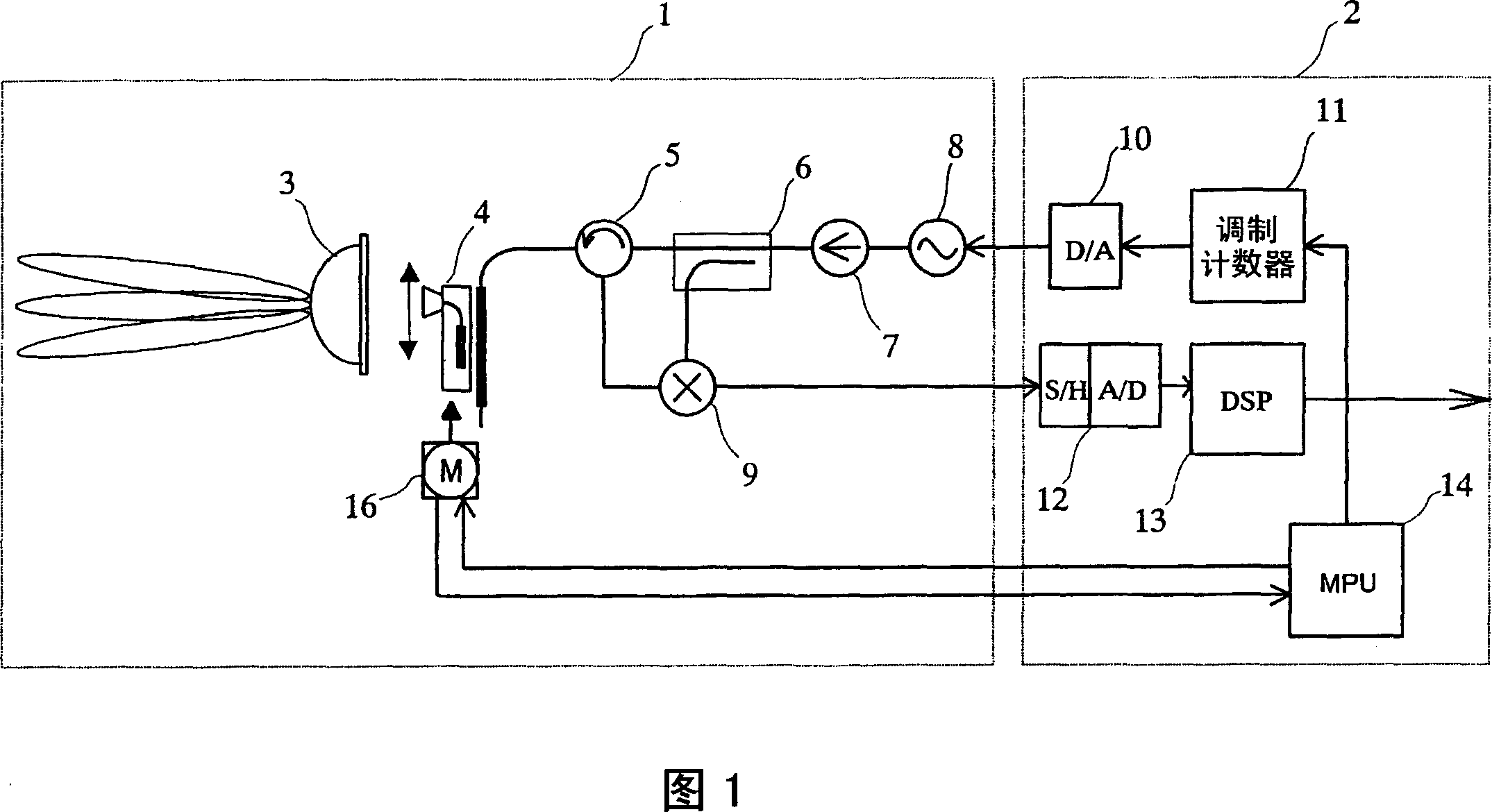
[0053] Fig. 1 is a block diagram showing the configuration of a radar system according to an embodiment of the present invention.

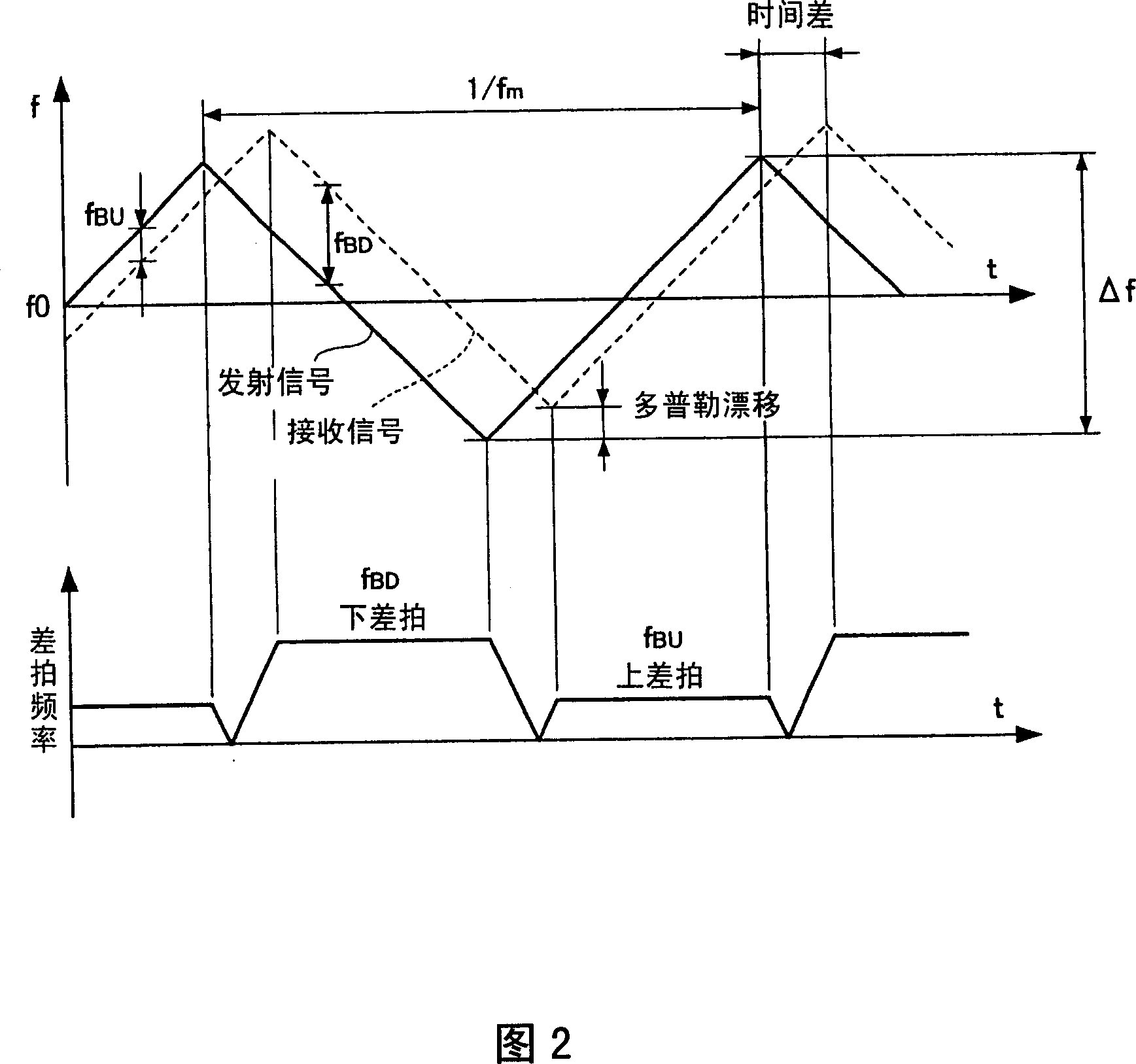
[0054] Referring to FIG. 1, reference numeral 1 denotes a radio frequency (RF) module, and reference numeral 2 denotes a signal processor module. The RF module 1 transmits and receives radio for measurement with a radar system, and supplies a difference frequency signal generated from the transmitted wave and the received wave to the signal processor module 2 . The modulation counter 11 in the signal processor module 2 performs counting, and provides the counted value to a digital-to-analog (DA) converter 10, so that the DA converter 10 generates a triangular wave signal. The DA converter 10 converts the supplied value into an analog voltage signal, and supplies the analog voltage signal to a voltage-controlled oscillator (VCO) 8 in the RF module to perform frequency modulation on a transmission wave. The oscillating signal from the VCO 8 is supp...


PUM


Abstract

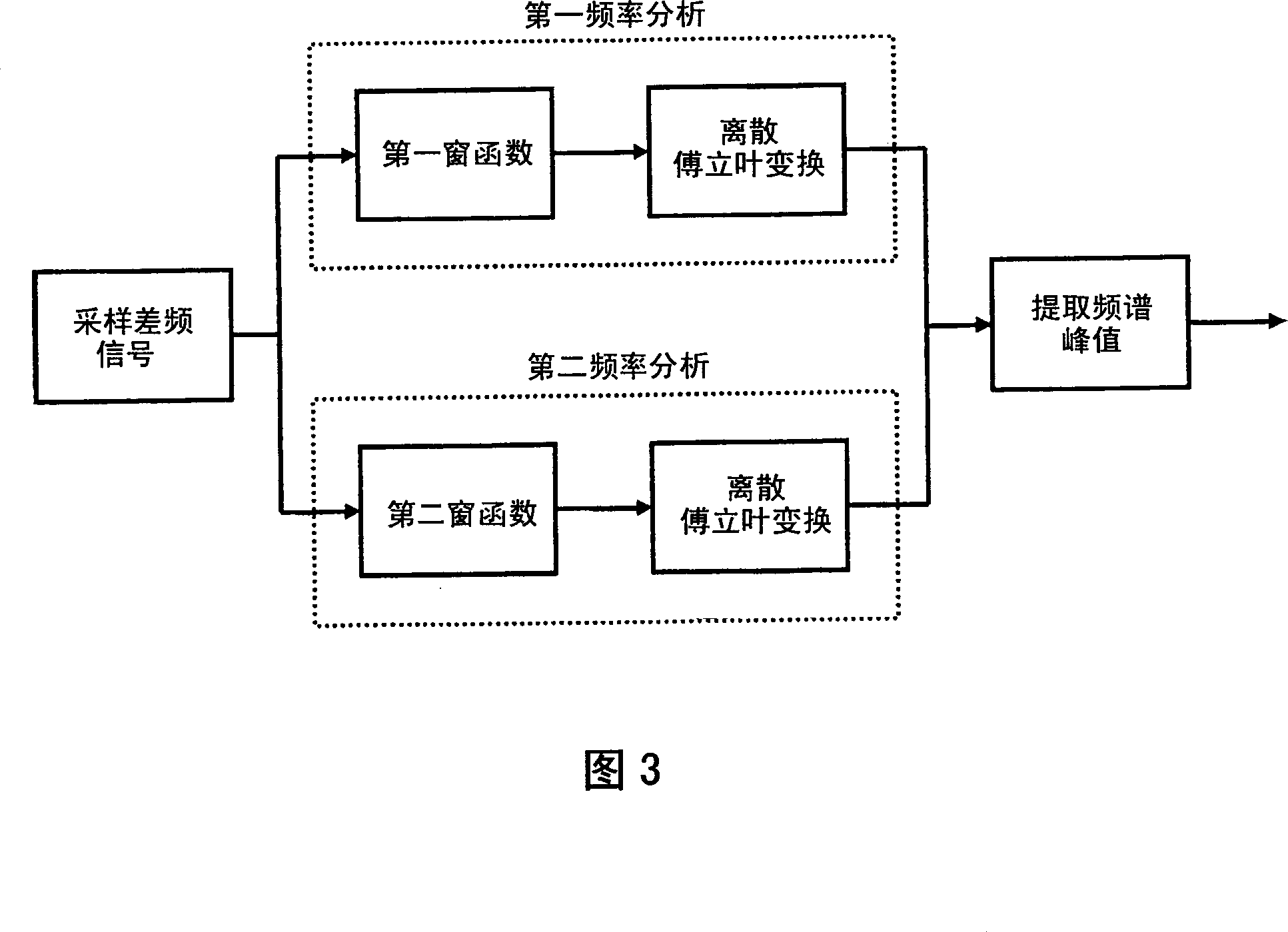
A radar system in which a beat signal is generated by transmitting a transmission signal that is subjected to frequency modulation into a triangular wave and receiving a reflection signal from a target, the beat signal is sampled, and a window function is applied to yield a discrete frequency spectrum. When the window function is applied, a first window function having an amplitude that is gently attenuated from the center of the sampling period toward both sides thereof is applied in a lower frequency band in the frequency spectrum (at close range), and a second window function having an amplitude that is sharply attenuated from the center of the sampling period toward both sides thereof is applied in a higher frequency band in the frequency spectrum (at far range).

Description

technical field [0001] The present invention relates to a system for detecting objects using radio waves. More specifically, it relates to a radar system that detects targets based on the spectrum of a difference frequency signal generated by a transmitted signal and a received signal. Background technique [0002] An FM-CW (Frequency Modulated Continuous Wave) radar system using millimeter radio waves has been developed as a vehicle-mounted radar system. In the FM-CW radar system, radio waves are subjected to frequency modulation within a predetermined frequency range around a predetermined frequency, and a difference frequency signal is generated from a transmitted signal and a received signal. Identify the beat frequency of the beat signal during up-modulation and during down-modulation to calculate the distance from the antenna to the target, and the relative velocity of the target relative to the antenna, where, during up-modulation, the frequency of the transmitted si...

Claims


Application Information

Patent Timeline
Patent Type & Authority Applications(China)
IPC IPC(8): G01S13/34G01S13/931
CPCG01S2007/356G01S13/345G01S13/426G01S13/931G01S2013/9375G01S2013/93271G01S7/356
Inventor 西村哲石井彻
Owner MURATA MFG CO LTD
Learn More