Electric vehicle chassis
An electric scooter and underframe technology, which is used in motor vehicles, vehicle ambulance, bicycles, etc., can solve the problems of increased activity space and uncomfortable passengers, and achieves a small turning radius, good safety, and convenience for users. Effects used within
- Summary
- Abstract
- Description
- Claims
- Application Information
AI Technical Summary
Problems solved by technology
Method used
Image

Examples
Embodiment 1
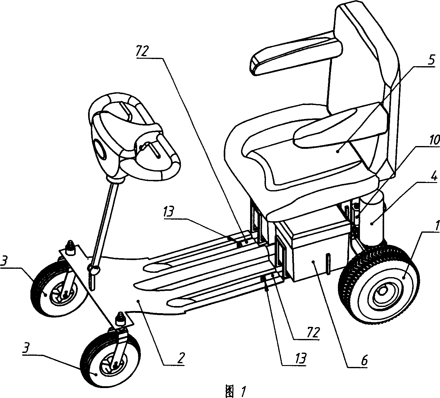
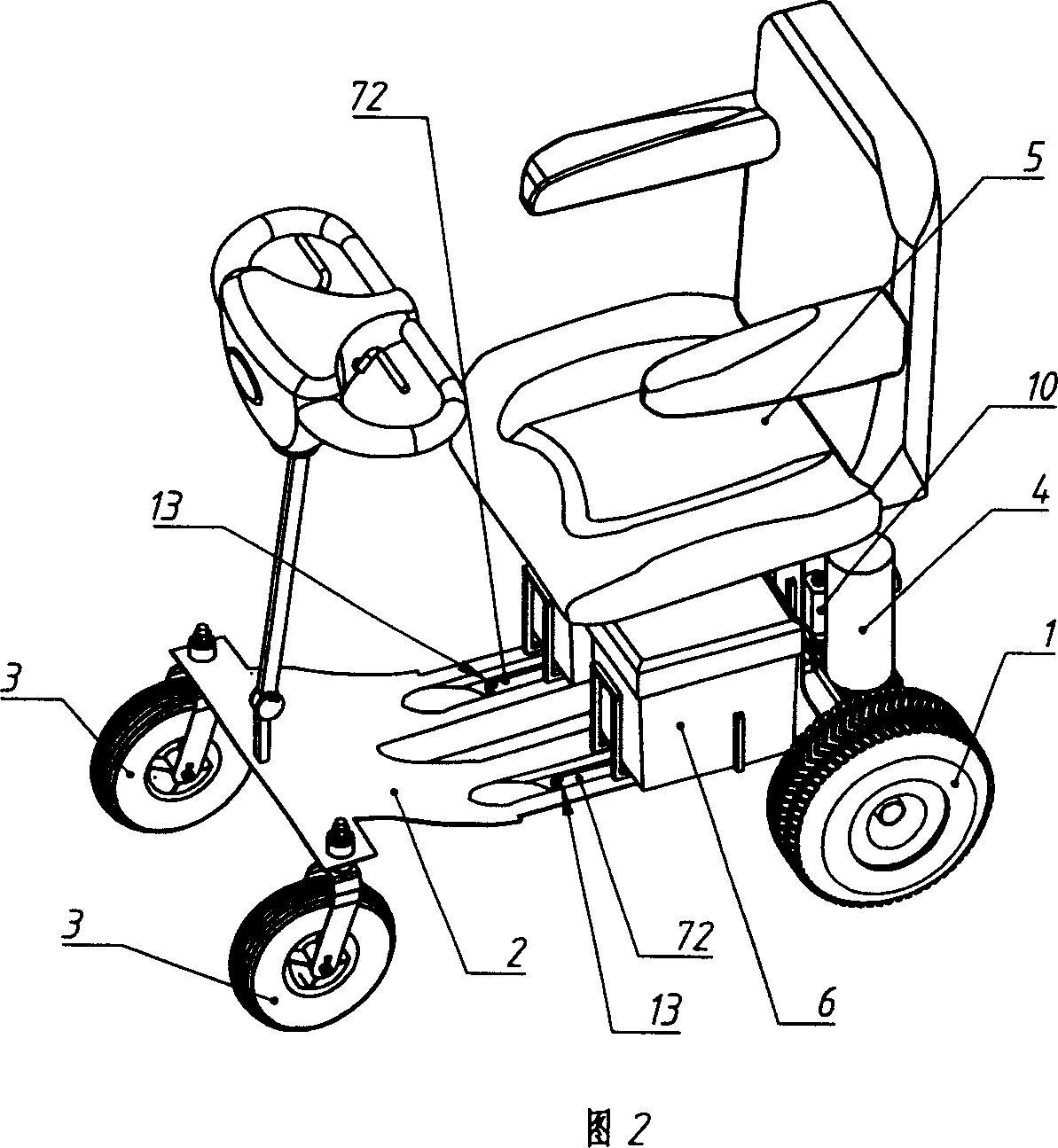
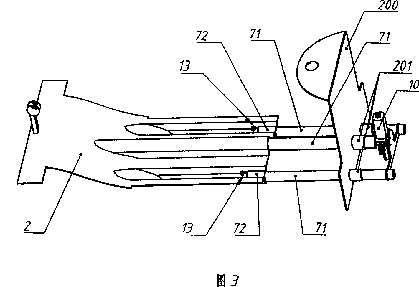
[0022] This example is based on the general description, mainly for the number of sliding pairs, their arrangement and their related institutional relationships. In this example, there are three pairs of sliding pairs arranged in parallel, and the telescopic drive mechanism is installed in the pair of sliding pairs in the middle (refer to Fig. 3, Fig. 4). Foot pedal 2 is fixed on the chassis at this end of walking wheel 3, and three grooves are respectively accommodated and fixed to the outer casing 72 of these three pairs of sliding pairs on this foot pedal 2. Two pairs of sliding pairs on both sides are equipped with anti-off mechanisms, or any pair of sliding pairs is equipped with anti-off mechanisms, or all three pairs of sliding pairs are equipped with anti-off mechanisms (Fig. Two pairs of sliding pairs are equipped with the structure of the anti-off mechanism). Above-mentioned pedal 2 generally can be stamped with steel plate, and the purpose of arranging groove is to...
Embodiment 2
[0030] This example is still on the basis of the general description, mainly for the number of sliding pairs, their arrangement and their related institutional relationships. In this example, the sliding pairs are a centrally arranged pair (see Figure 5). In this case, the inner and outer sleeves (71, 72) of the sliding pair are rectangular sleeves or other sleeves with a circumferential limit structure for preventing rotation. That is to say, the inner and outer sleeves can also be oval, triangular, etc. non-circular, and the circular tube can also be provided with a sliding key and its corresponding keyway to prevent rotation. On the chassis at this end of the walking wheel 3, a pedal 2 is fixed, on which there is a groove that accommodates and fixes the outer sleeve 72 of the sliding pair (the concave surface of the groove in the figure faces upwards) . Both the telescopic drive mechanism and the anti-off mechanism are installed in the pair of sliding pairs. Certainly, s...
Embodiment 3
[0032] This example is also an example based on the general description, mainly for the number of sliding pairs, their arrangement and their related institutional relationships. In this example, there are two pairs of sliding pairs arranged in parallel, and the telescopic drive mechanism is installed in the middle of these two pairs of sliding pairs (refer to FIG. 6 ). Foot pedal 2 is fixed on the underframe at walking wheel 3 this end, and there are two grooves in which the outer sleeve 72 of these two pairs of sliding pairs is accommodated and fixed respectively at the top of this pedal 2 . Two pairs of sliding pairs on both sides are all equipped with anti-off mechanisms, or any pair of sliding pairs is equipped with anti-off mechanisms (drawing in the figure is that two pairs of sliding pairs on both sides are all equipped with anti-off mechanisms). Identical with preceding two examples, should add a piece of rubber or the plastic pedal pad (not drawn among the figure) tha...
PUM
 Abstract
Description
Claims
Application Information
 - R&D
- Intellectual Property
- Life Sciences
- Materials
- Tech Scout
- Unparalleled Data Quality
- Higher Quality Content
- 60% Fewer Hallucinations
Browse by: Latest US Patents, China's latest patents, Technical Efficacy Thesaurus, Application Domain, Technology Topic, Popular Technical Reports.
© 2025 PatSnap. All rights reserved.Legal|Privacy policy|Modern Slavery Act Transparency Statement|Sitemap|About US| Contact US: help@patsnap.com