Direct buried underground heat exchanger of engineering abandored water lowering well

A technology of underground heat exchangers and dewatering wells, which is applied in the direction of indirect heat exchangers, geothermal collectors, heat exchangers, etc., can solve the problem of heat preservation of near-surface pipelines in winter, complicated construction of coil heat exchangers, Affect the heat exchange efficiency of the soil layer and other issues, to achieve the effect of eliminating groundwater pollution, avoiding groundwater resource usage fees, and increasing heat exchange efficiency

Inactive Publication Date: 2007-04-11
张延军 +1
View PDF2 Cites 13 Cited by
  • Summary
  • Abstract
  • Description
  • Claims
  • Application Information

AI Technical Summary

Problems solved by technology

Although some people in foreign countries have mentioned the concept of pile-buried heat exchangers, they are all based on high-strength polyethylene U-shaped coil concrete poured solid section piles (Laloui Lyesse, Moreni Matteo, Vulliet Laurent, Behavior of a bi-functional pile, foundation and heat exchanger, Canadian Geotechnical Journal, v 40, n 2, April, 2003, p 388-402.), these disadvantages based on drilling or embedding tubular heat exchangers in various concrete pouring piles are: high drilling costs, The construction of the coil heat exchanger in the concrete pouring pile is complicated, requiring processes such as coil binding and steel cage
It only considers that the tubular heat exchanger is a set of U-shaped coils or open tube-like tubular heat exchangers. Their heat exchanger efficiency is not high, and no backfill material is added to the hollow pile core of the pipe pile. , which directly affects the heat transfer efficiency with the soil layer
In addition, when pipe piles are used as enclosure piles or pile tops near the surface, the problem of pipeline insulation near the surface in winter is not considered

Method used


Image

  • Direct buried underground heat exchanger of engineering abandored water lowering well
  • Direct buried underground heat exchanger of engineering abandored water lowering well
  • Direct buried underground heat exchanger of engineering abandored water lowering well

Examples


Embodiment Construction

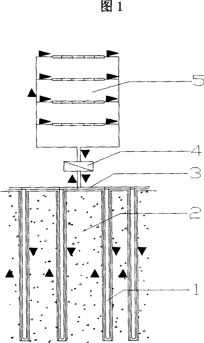
[0019]In Figure 1, the ground source heat pump utilizes the low-temperature thermal energy of the shallow geothermal resources on the surface. The heat in the soil layer (2) is extracted and supplied to the building (5) for heating through the surface exchange pipeline (3) and the ground source heat pump unit (4); in summer, the heat of the building (5) is extracted and passed through the surface exchange pipe The heat exchange fluid in the road (3), the ground source heat pump unit (4) and the directly buried underground heat exchanger (1) of the abandoned dewatering well of the project is released into the shallow soil layer (2).

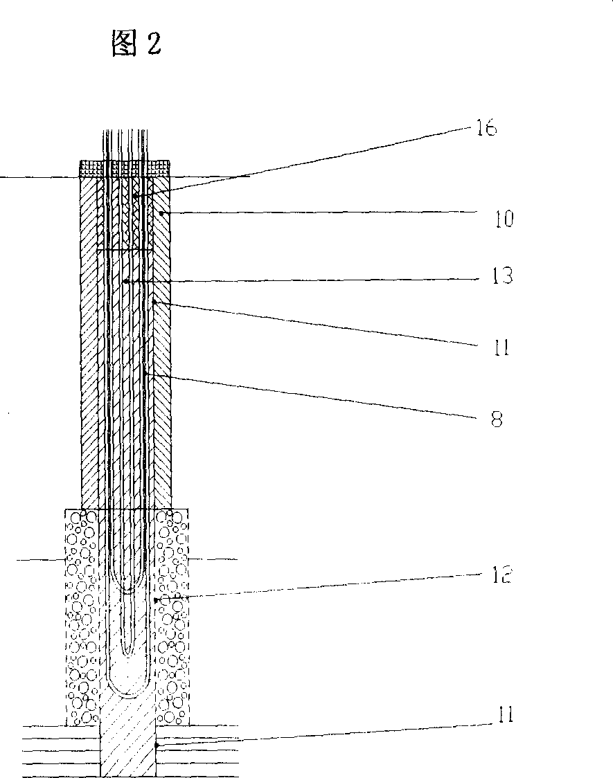
[0020] In the embodiment shown in Fig. 2, the direct-buried subterranean heat exchanger (1) of the dewatering well in engineering scrapping has multiple regulations for its sealing, and the structure of the normal whole well is filled with gravel (10) outside the well casing, The well casing is composed of a sand settling pipe (11) and a water fil...


PUM


Abstract

The present invention is direct buried underground heat exchanger formed through reforming used engineering precipitating well. While the engineering precipitating well after completing normal precipitating task is refilled, U-pipe heat exchanger, spiral pipe heat exchanger or other tubular heat exchanger is inserted, well closing material is filled between the well wall and the heat exchanger, heat insulating material is filled near the well top, and the heat exchanger is connected to ground pipeline. By means of pumping out water and refilling water and the underground heat exchange, a closed geothermal heat pump type underground heat exchanger is formed.

Description

Technical field: [0001] The invention relates to the combination of sealing and filling technology of scrapped dewatering wells of construction engineering and closed ground source heat pump technology, and is a direct-buried underground heat exchanger that uses tubular heat exchanger devices inserted into dewatering wells of scrapped projects to convert low-temperature geothermal energy , the device is a multifunctional direct-buried underground heat exchanger that can not only safely seal and fill the abandoned precipitation wells of construction projects, but also has low-temperature geothermal energy cycle heat exchange capabilities. Background technique: [0002] At present, known engineering dewatering wells mainly refer to tube wells serving engineering dewatering, and their use time limit is limited, generally ending with the completion of the main project or excavation engineering construction. The discarded precipitation wells must be sealed and filled in time, oth...

Claims


Application Information

Patent Timeline
Patent Type & Authority Applications(China)
IPC IPC(8): F24J3/08F28D7/00E02D19/10E02D19/12
CPCY02E10/125F24J3/083F24T10/15Y02E10/10
Inventor 张延军
Owner 张延军
Why Eureka
Try Eureka