Ink sucking device of jetting-drawing machine

A technology of an inkjet printer and a traction device, which is applied to printing and other directions, can solve problems such as affecting production efficiency, drying the ink-absorbing tube, and increasing labor intensity of workers, and achieves the effects of reducing labor intensity, simple structure, and improving production efficiency.

Active Publication Date: 2007-04-18
SHENZHEN RUNTIANZHI DIGITAL EQUIP
View PDF0 Cites 10 Cited by
  • Summary
  • Abstract
  • Description
  • Claims
  • Application Information

AI Technical Summary

Problems solved by technology

[0003] In the above method, when the ink ejection hole is blocked, the nozzle head must be removed for special cleaning, and, during the suspension of the machine, the ink ejection hole is not closed, and the ink in the ink suction channel will flow out, causing the ink suction line to be damaged. It is easy to dry out, so that the machine needs a longer preparation time to wet the inkjet pipeline when it works next time. Therefore, the above method of dredging the clogged inkjet hole increases the labor intensity of the workers and seriously affects the production efficiency.
[0004] In addition, in the prior art, in order to avoid certain parts of the staff and the machine from being irradiated by the UV lamp, when cleaning the nozzle of the inkjet printer with the UV lamp, a shading plate is placed under the stop position of the UV lamp. The shading device and the waste ink collection device are two independent devices, which makes the structure of the inkjet printer more cumbersome

Method used


Image

  • Ink sucking device of jetting-drawing machine
  • Ink sucking device of jetting-drawing machine
  • Ink sucking device of jetting-drawing machine

Examples


Embodiment Construction

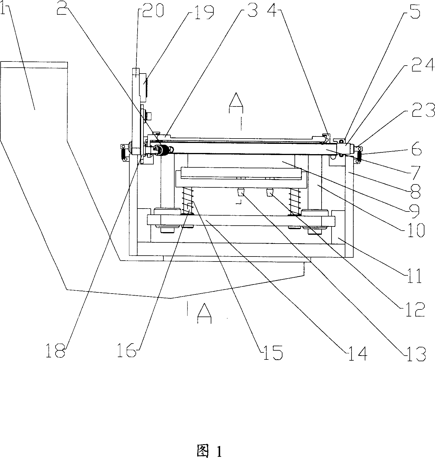
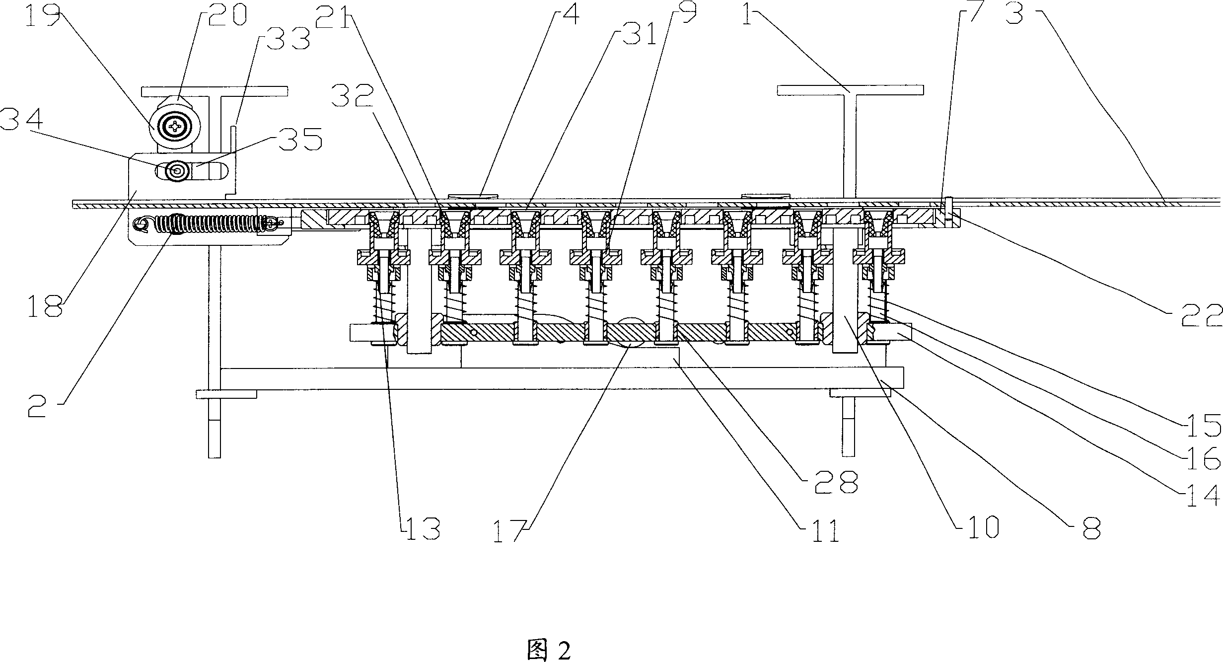
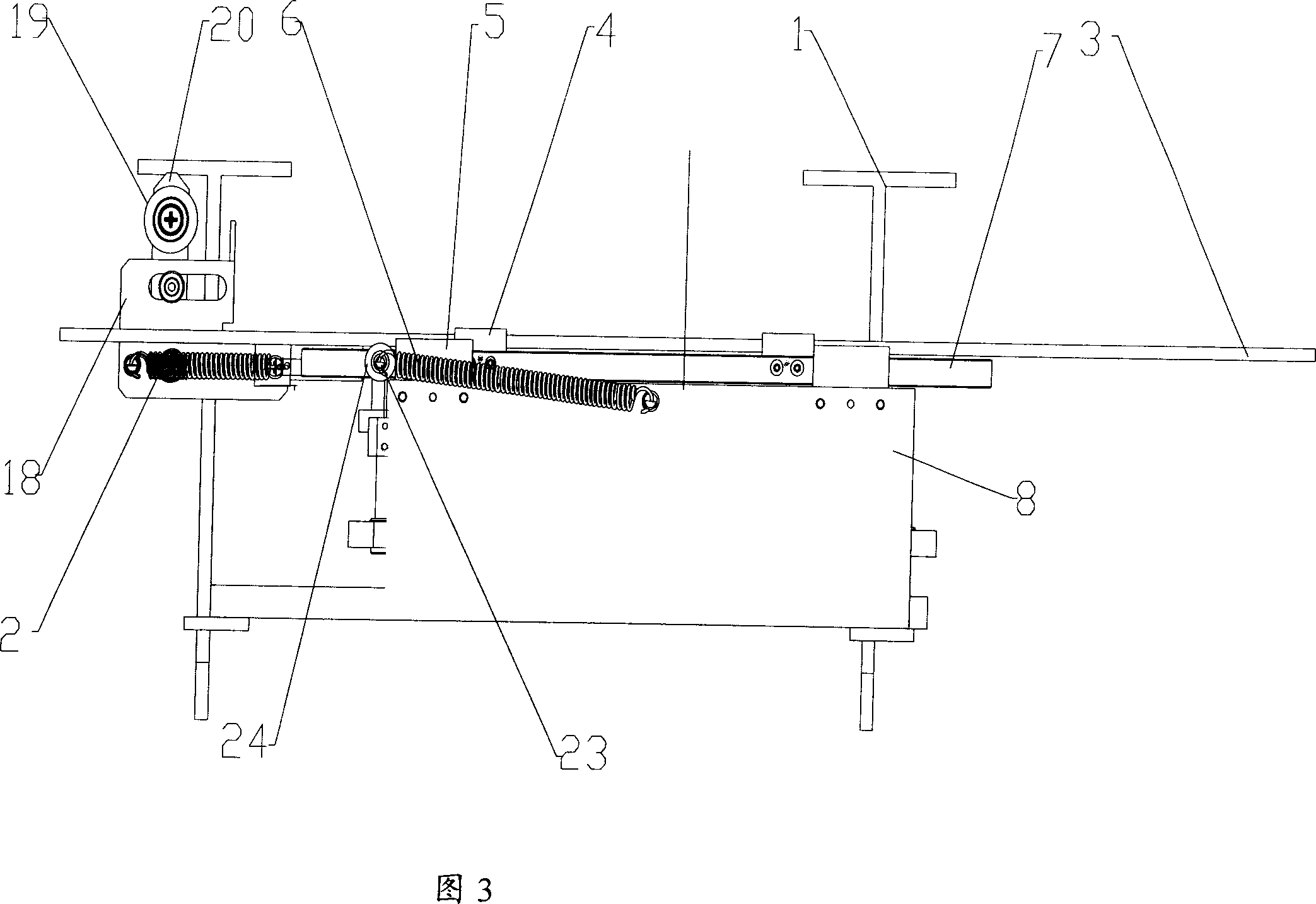
[0023] As shown in FIG. 1 and FIG. 2 , the ink suction device of the inkjet printer provided by the present invention mainly includes a bracket 1 , a base 8 , a tray 7 , a lifting plate 14 and a suction bar seat 9 . The base 8 of the present invention is fixed on the support 1, wherein, as shown in Figure 4, the support 1 is fixed on the guide rail beam 25, and the upper part of the base 8 is fixed with two rows of pallet ball guide rails 5 parallel to the slide rails of the nozzle trolley 27. A tray 7 is placed on the ball guide rail 5, and the tray 7 is provided with through slots 31 corresponding in quantity and position to the nozzles 26. On the ink hole, one end of the tray 7 protrudes and fixes a passive rod 20 near the position of the end of the support 1. The upper end of the passive rod 20 is provided with a roller two 19, and the middle part of the passive rod 20 is provided with a roller three 34. Wherein, if the inkjet printer has UV lamp, as shown in Figure 1 and ...


PUM


Abstract

An ink sucking device for ink-jet plotter is composed of base, tray and its ball track, passive rod fixed to one end of tray, guide posts of lift plate fixed to 4 corners of tray, lift plate with rollers at its both sides, oblique plate for bearing said rollers, sucking strip and its guide column, sucking strip holder, and traction unit.

Description

technical field [0001] The invention relates to an ink absorbing device for an inkjet printer, in particular to a fully mechanically controlled and sealed ink absorbing device for an inkjet printer. Background technique [0002] At present, in the maintenance of large-scale inkjet printers, the main method of unblocking the blocked inkjet holes is to remove the nozzle for special cleaning. The ink tray catches the ink flowing out of the nozzle, and to shield the ultraviolet light (UV light), a shading plate is placed under the position where the UV light stays. [0003] In the above method, when the ink ejection hole is blocked, the nozzle head must be removed for special cleaning, and, during the suspension of the machine, the ink ejection hole is not closed, and the ink in the ink suction channel will flow out, causing the ink suction line to be damaged. It is easy to dry out, so that the machine needs a longer preparation time to wet the inkjet pipeline when it works nex...

Claims


Application Information

Patent Timeline
Patent Type & Authority Applications(China)
IPC IPC(8): B41J2/165B41J2/185
Inventor 江洪
Owner SHENZHEN RUNTIANZHI DIGITAL EQUIP
Why Eureka
Try Eureka