Catalytic conversion method of double reactor and its device

A catalytic conversion method and reactor technology, applied in the field of catalytic conversion methods and devices, can solve the problems of complex device, difficult implementation, large investment, etc., and achieve the effects of device simplification, low contact temperature, and gasoline olefin content reduction.

Inactive Publication Date: 2007-04-18
石宝珍
View PDF6 Cites 6 Cited by
  • Summary
  • Abstract
  • Description
  • Claims
  • Application Information

AI Technical Summary

Problems solved by technology

However, it is still necessary to build a gasoline settler, the device is complicated, the investment is large, and it is not easy to implement

Method used


Image

  • Catalytic conversion method of double reactor and its device
  • Catalytic conversion method of double reactor and its device
  • Catalytic conversion method of double reactor and its device

Examples


Embodiment 1

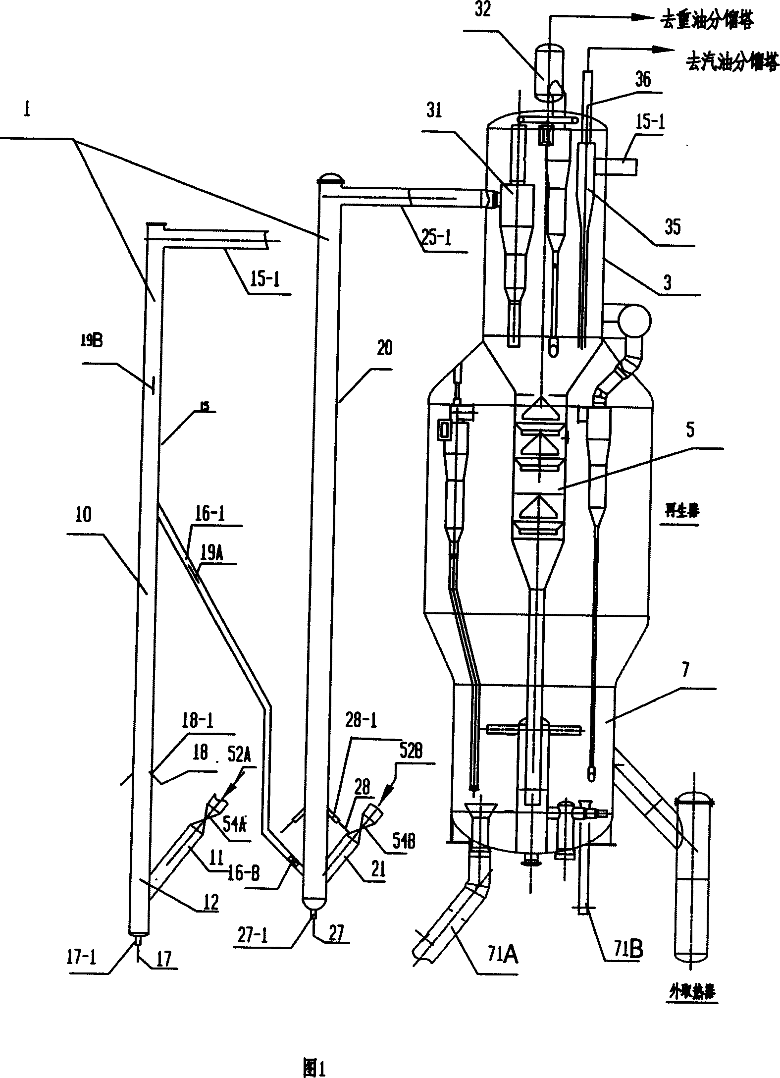
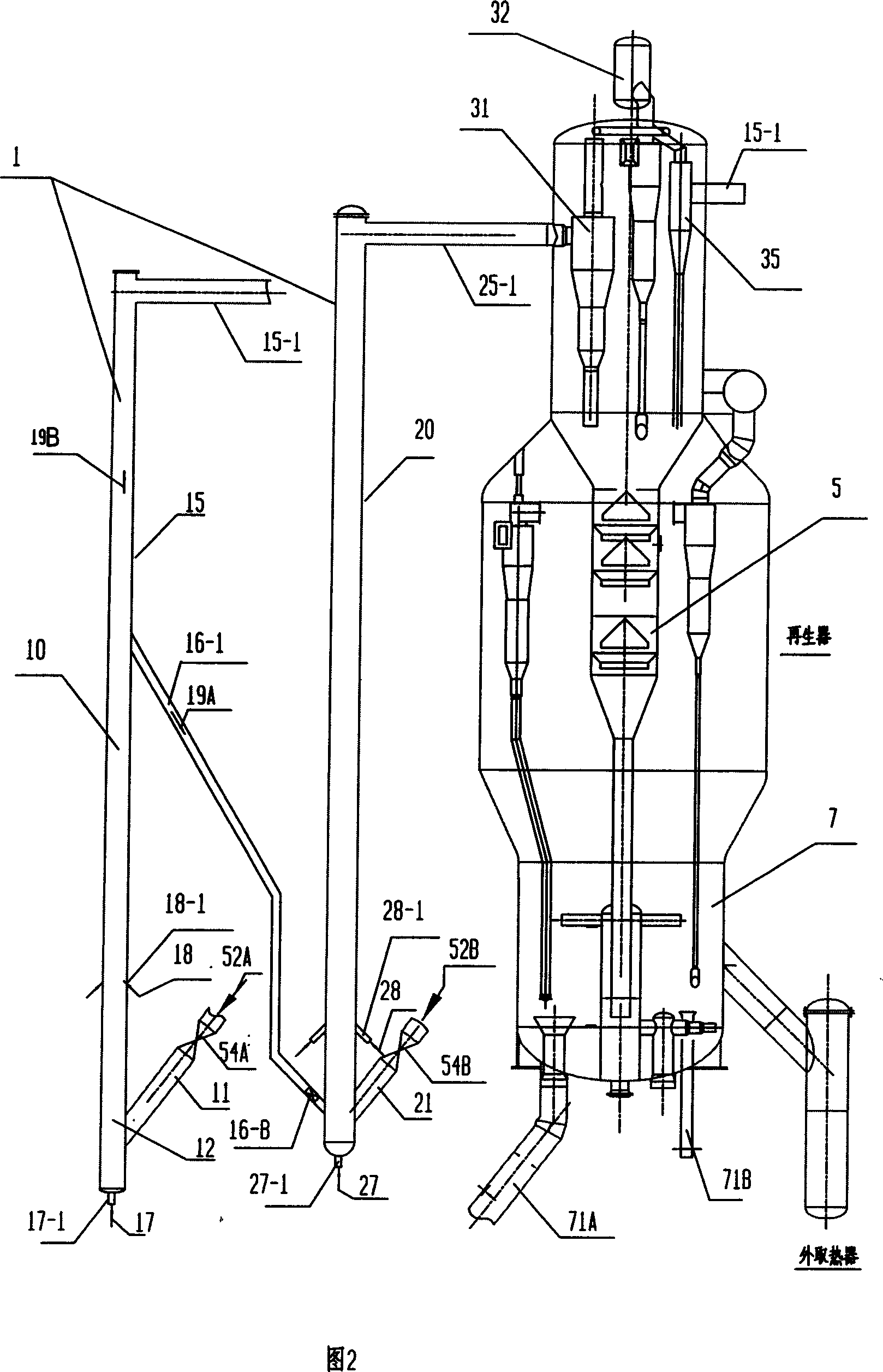
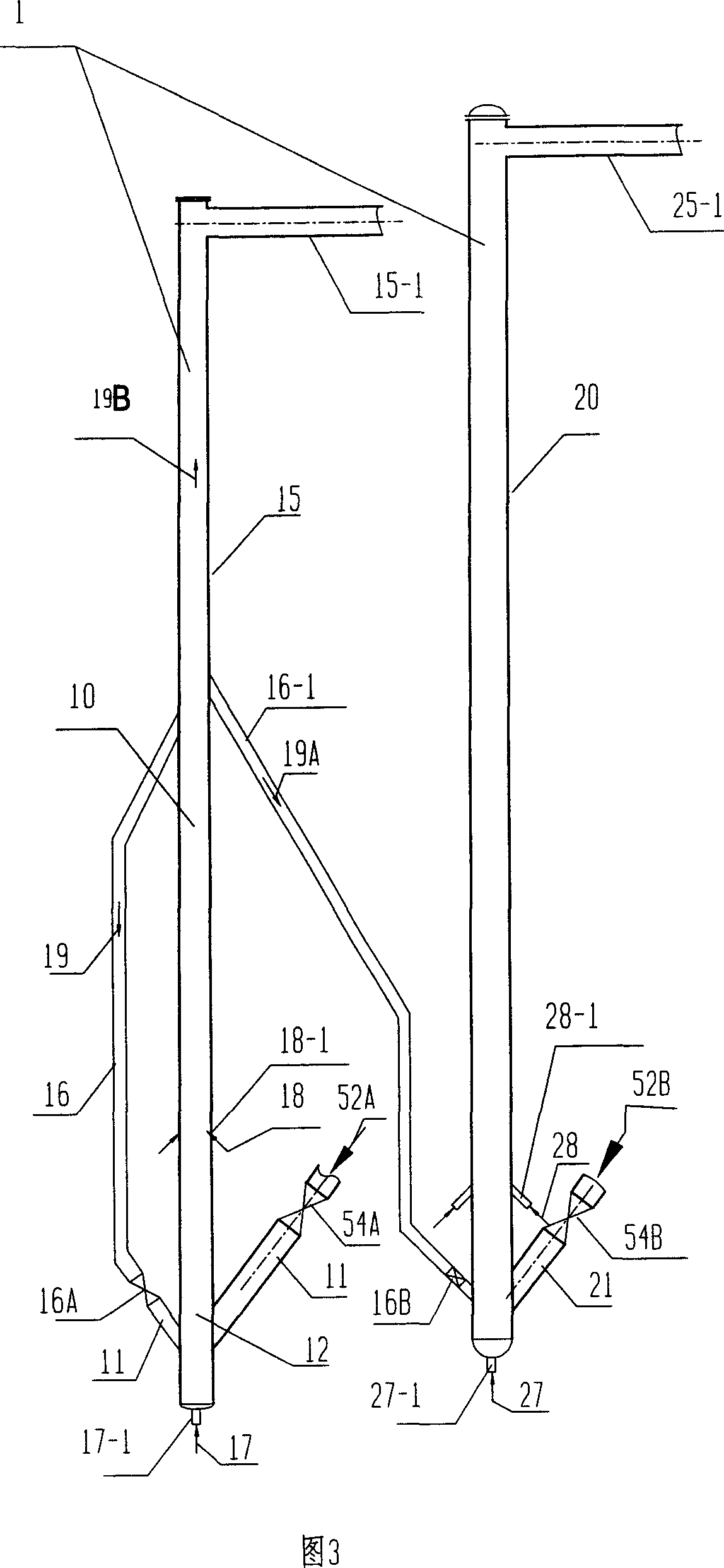
[0032] Example 1. The reaction materials are: pipeline transportation of heavy oil at atmospheric pressure, 100t / h heavy oil, gasoline feedstock is heavy oil reaction self-produced gasoline, with the main purpose of producing low olefin gasoline; heavy oil preheating 220°C, gasoline 40°C; gasoline reaction The reactor uses the patent application number 200510017986.4, and the heavy oil reactor is in the form of a riser; the gasoline and heavy oil reaction products are separated, and enter their respective fractionation towers through their respective oil and gas pipelines for product separation. The heavy oil enters the riser in four ways, and the gasoline enters the reactor in two ways; the reaction temperature of heavy oil is 500°C, the reaction time is 2.5s, the reaction temperature of gasoline is 430°C, and the reaction time is 3s; The temperature of the catalyst before the reaction in the vessel is 600°C; the regeneration temperature is 690°C.

[0033] The device used in ...

Embodiment 2

[0037] Example 2. The reaction materials are: Daqing atmospheric heavy oil, 100t / h heavy oil, gasoline feedstock is heavy oil to react self-produced gasoline; heavy oil is preheated at 220°C, gasoline is at 40°C; the heavy oil reactor is in the form of a riser, and the gasoline reactor is a riser gasification The heavy oil enters the riser in four ways, and the gasoline enters the reactor in two ways; the reaction temperature of heavy oil is 515°C, and the reaction time is 2.5s; the reaction temperature of gasoline is 525°C, and the reaction time is 4s. The residence time in the chemicalization section is 0.5s, and the residence time in the middle fast fluidized bed is 3.5s; the superficial flow velocity of oil and gas in the fluidized bed is 4.0m / s; The catalyst temperature is 620°C; the regeneration temperature is 690°C. The device form used is shown in Fig. 1, wherein the reactor part uses the type shown in Fig. 4.

[0038] Comparative example: The heavy oil reaction part...


PUM


Abstract

This invention provides a catalytic cracking method, and it will make sure that raw material oil and petroleum react separately in their own demands by using coupling reactors. In order to improve agent-oil ratio, the accelerant with low temperature from petroleum reaction reenters into the pre-upgrading section of raw material oil reaction. It will low the temperature of accelerant of petroleum reaction and improve agent-oil ratio before low temperature accelerant from petroleum reaction recirculating into petroleum reactor before feeding material. The equipment of this catalytic cracker uses coupling reactor, and the accelerant after the reaction of petroleum will be directly send into the pre-promotion section of heavy oil reactivation from petroleum reactor by accelerant transport pipe between the petroleum reactor and heavy oil reactor. The accelerant recirculating pipe designed with petroleum reactor to make part of the accelerant return to petroleum reactor before feeding material. The catalytic cracking equipment is a settling vessel, which will separate the oil gas from different reactor and enter their own fractionating tower to form the program of single settling vessel and coupling fractionating tower to receive pure petroleum upgrading product.

Description

technical field [0001] The invention belongs to the technical field of catalytic conversion of petroleum hydrocarbons, in particular to a catalytic conversion method and device capable of increasing catalytic cracking yield and improving product quality. Background technique [0002] Catalytic cracking is an important secondary processing method for petroleum heavy fractions. Especially in China, about 80% of gasoline comes from catalytic cracking units. How to increase the product yield of the catalytic cracking unit and improve the product quality are very important. Conventional catalytic cracking methods and devices use riser reactors, which have obvious deficiencies in the reaction process. First of all, the temperature of the regenerant is high, which limits the ratio of reactant to oil and the preheating temperature of heavy oil; it affects the product yield; in addition, the product quality of the catalytic cracking unit is not ideal, especially the olefin content ...

Claims


Application Information

Patent Timeline
Patent Type & Authority Applications(China)
IPC IPC(8): C10G55/08
Inventor 石宝珍
Owner 石宝珍
Why Eureka
Try Eureka