Fuel supply device for a motor vehicle

A technology for fuel supply and motor vehicle, which can be applied to the layout, power plant, machine/engine, etc. combined with the fuel supply of internal combustion engines, and can solve the problem of high cost

Inactive Publication Date: 2007-04-18
CONTINENTAL AUTOMOTIVE GMBH
View PDF0 Cites 7 Cited by
  • Summary
  • Abstract
  • Description
  • Claims
  • Application Information

AI Technical Summary

Problems solved by technology

A disadvantage of the [0003] known fuel supply is that the suction injection pump is expensive to install in the breather and requires Part of the flow as power fuel

Method used


Image

  • Fuel supply device for a motor vehicle
  • Fuel supply device for a motor vehicle
  • Fuel supply device for a motor vehicle

Examples


Embodiment Construction

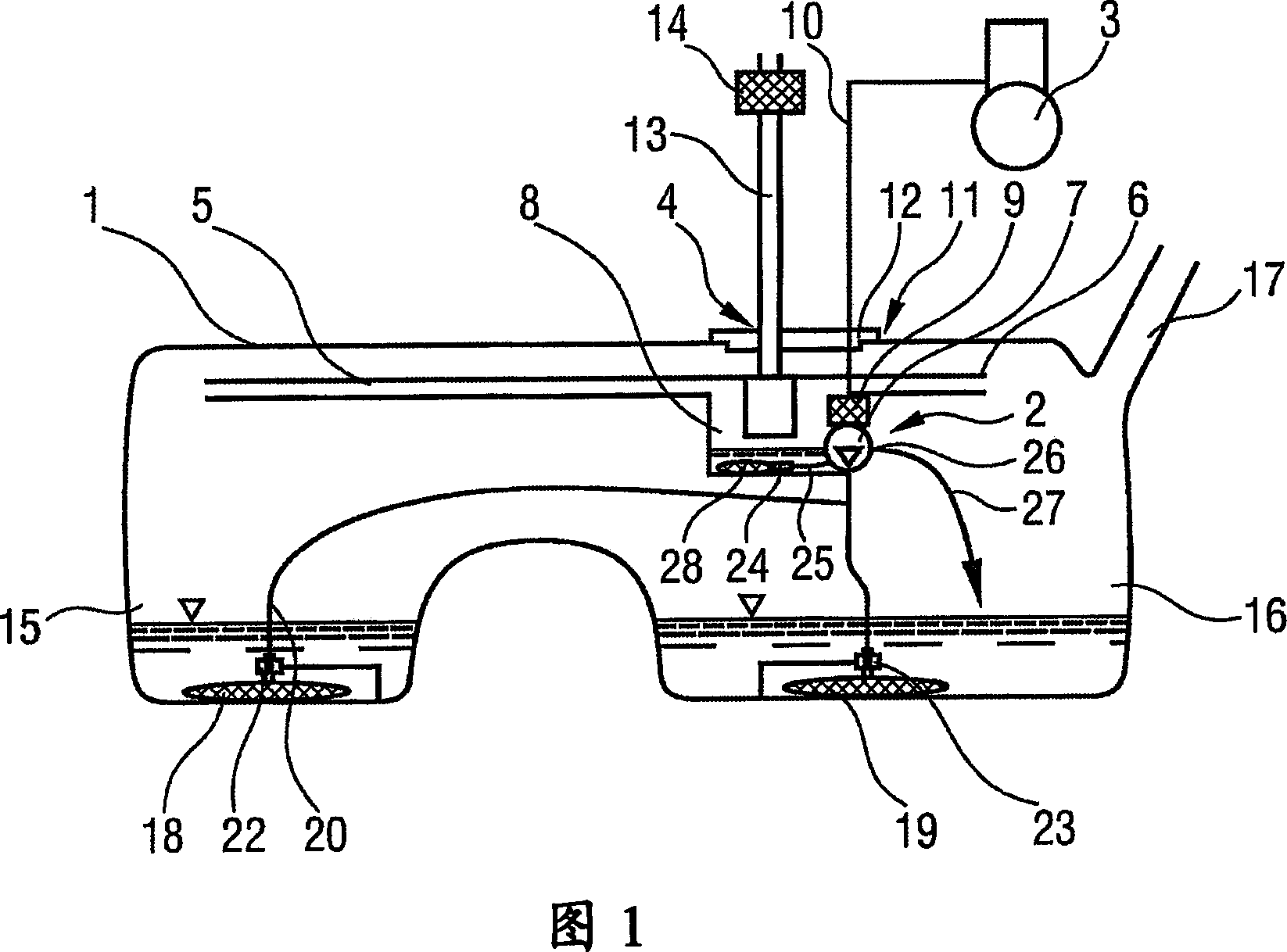
[0024] FIG. 1 shows schematically a fuel tank 1 in a schematic sectional view with a fuel supply device 2 for supplying fuel to an internal combustion engine 3 of a motor vehicle. A breather 4 with a plurality of breather lines 5 , 6 and a fuel pump 7 are arranged inside the fuel tank 1 . The fuel pump 7 forms a structural unit with the defoaming container 8 of the breather 4 . The fuel supply line 10 leading from the fuel pump 7 via the filter 9 to the internal combustion engine 3 passes through a sealing cap 12 fastened in a mounting opening 11 in the fuel tank 1 .

[0025] The breather 4 is connected via an air outlet line 13 to an activated carbon filter 14 arranged outside the fuel tank 1 . The air outlet duct 13 likewise passes through the sealing cover 12 . The activated carbon filter 14 establishes a pressure equalization between the fuel tank 1 and the environment via the breather 4 . The defoaming container 8 collects the fuel that is present in the breather 4 . ...


PUM


Abstract

The invention relates to a fuel supply device (2) for a motor vehicle, which comprises a fuel tank (1). An intake connection (24) of a fuel pump (7) is located in a ventilation device (4). The fuel pump (7) simultaneously takes in fuel from the fuel tank (1) and from the ventilation device (4). For this purpose, the fuel pump (7) and a bubble removal container (8) of the ventilation device (4) are configured as a single structural unit.

Description

technical field [0001] The invention relates to a fuel supply device for a motor vehicle, the fuel supply device has: a fuel tank; a fuel pump, which draws fuel from the fuel tank and delivers the fuel to the internal combustion engine of the motor vehicle; Used to balance the pressure of the fuel tank with the external environment; device used to draw and discharge the fuel in the breather to the fuel tank. Background technique [0002] Such fuel supply devices are frequently used in existing motor vehicles and are well known in practice. In the known fuel supply device, the fuel pump is separate from the breather, attached to the bottom of the fuel tank, and delivers the fuel into the fuel supply line to the internal combustion engine of the motor vehicle. Branch off from the oil supply line is a line leading to a suction jet pump arranged in the breather. A suction injection pump delivers fuel from the breather to the fuel tank. Components of the breather are also fitt...

Claims


Application Information

Patent Timeline
Patent Type & Authority Applications(China)
IPC IPC(8): B60K15/035F02M37/10F02M37/20
CPCF02M37/106B60K15/03504F02M37/20B60K2015/03509Y10T137/2496B60K2015/03467B60K15/035
Inventor 斯特凡·菲林赫尔穆特·科尔哈斯克里斯蒂安·克罗格尔克努特·迈尔弗兰克·赖特尔
Owner CONTINENTAL AUTOMOTIVE GMBH
Why Eureka
Try Eureka