
Mechanical pressure machine control method for slider stopping at certain point

A mechanical press, dead center position technology, applied in presses, manufacturing tools, etc., can solve problems such as life impact, braking performance decline, and inability to stop at the top dead center, achieve strong application and promotion value, and reduce adjustment. The number of times, the effect of improving the positioning accuracy

Active Publication Date: 2007-04-25
NANJING ESTUN AUTOMATION CO LTD
View PDF0 Cites 16 Cited by
  • Summary
  • Abstract
  • Description
  • Claims
  • Application Information

AI Technical Summary

Problems solved by technology

The disadvantage of this method is that it cannot be guaranteed to stop at the top dead center when the speed of the slider changes and the friction plate is worn. Every time the cam angle is adjusted, it needs to be manually adjusted, and a fixed angle is used as the braking angle.
Moreover, the disadvantage of this method is that once the friction plate of the clutch works for a long time, the braking performance will decrease; or when the speed changes or the air pressure changes, the slider cannot be guaranteed to stop at the top dead center.
Due to the need for manual adjustments, time is wasted, production efficiency is low, the number of actions of the clutch increases, and the service life is affected
However, there are strong nonlinearity and time lag between the braking angle of the clutch and the physical characteristics of the clutch itself, air pressure, flywheel speed and other factors, so it is difficult to establish an accurate mathematical model

Method used


Image

  • Mechanical pressure machine control method for slider stopping at certain point

Examples


Embodiment Construction

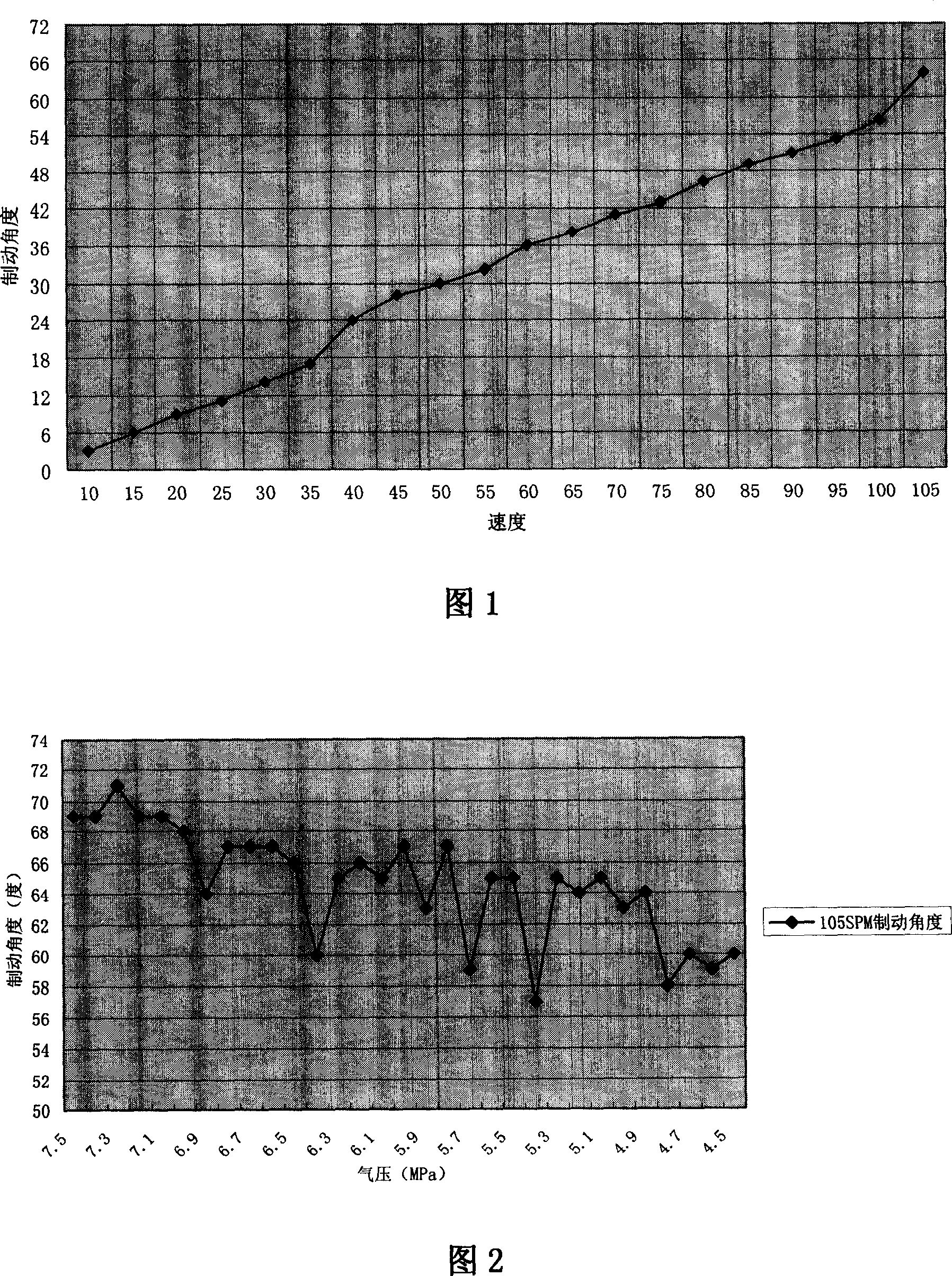
[0024] The relationship curve between the braking angle of the clutch and the speed of the slider is shown in Figure 1. Analyzing the graph, it can be approximated that the braking angle is directly proportional to the speed of the slider. Therefore, after we know the braking angles of two speed points, we can estimate the braking angles of other speed points. However, the braking angle is also related to the air pressure and the braking position of the clutch. At the same speed, when the air pressure is low, the braking angle is large, and when the air pressure is high, the braking angle is small. Refer to Figure 2 for the clutch braking angle curve at the same speed, because at the same speed, the braking angle is not only related to the air pressure, but also related to the position of the clutch brake, etc., so the air pressure and braking angle are not absolutely monotonous.

[0025] According to the above analysis results, the following braking algorithm is summarized: ...


PUM


Abstract

The invention relates to a method for controlling the compressor sliding block to stop at dead position. Wherein, it uses the rotation coder as the crank angle / block strike sensor of mechanical compressor, to feed collected angle information to the electric cam controller; the controller based on the crank angle information outputs cam signal, based on the passed angle in fixed time of crank to calculate out the crank speed. The invention is characterized in that: based on the brake angles of last two sliding blocks, it finds the incline factor of angle-speed curvature; when the compressor first operates in one sliding block speed, based on said factor, it can find the present brake angle; when the speed is stable, the brake angle will be automatically compensated referring to the shift from last brake angle; the brake angles in different speeds are stored; when the electric cam receives brake signal, based on preset speed to inquire database, and find out present brake angle; when block reaches said brake angle, outputting the brake signal.

Description

technical field [0001] The invention relates to a mechanical press, in particular to a method for controlling the top dead center position of a slider of a mechanical press, and belongs to the field of mechanical processing and computer automatic control. Background technique [0002] During mechanical press processing, the slider is generally required to stop at the top dead center position to ensure that there is enough energy to process the workpiece during stamping processing. In the past, the mechanical cam was used as the crankshaft angle detection device, and the logic control was realized by PLC. The disadvantage of this method is that it cannot be guaranteed to stop at the top dead center when the speed of the slider changes and the friction plate is worn. Every time the cam angle is adjusted, it needs to be manually adjusted, and a fixed angle is used as the braking angle. Moreover, the shortcoming of this method is that once the friction plates of the clutch work...

Claims


Application Information

Patent Timeline
IPC IPC(8): B30B15/14
Inventor 徐正华移振华
Owner NANJING ESTUN AUTOMATION CO LTD
Learn More