Vapor axial deposition apparatus and vapor axial deposition method

A vapor-phase axial deposition, vertical axis technology, used in glass deposition furnaces, glass manufacturing equipment, glass production, etc., can solve the problem of difficulty in maintaining focus, not fully considering the overall temperature distribution of soot preforms, and reducing the quality of soot preforms. question

Inactive Publication Date: 2007-04-25
SAMSUNG ELECTRONICS CO LTD
View PDF1 Cites 17 Cited by
  • Summary
  • Abstract
  • Description
  • Claims
  • Application Information

AI Technical Summary

Problems solved by technology

[0005] First, since a point on the end of the soot preform is monitored by an optical pyrometer placed under the soot preform, it is difficult to maintain focus due to the rotation and vibration of the soot preform
[0006] Second, due to the presence of soot and flame between the end of the soot preform and the optical pyrometer, a lot of noise is included in the optical pyrometer measurements due to the interference of soot and flame
[0007] Therefore, the vapor-phase axial deposition method as described above has a problem that its mass-production capability and reliability are reduced due to the difficulty in accurate temperature measurement and control of the end of the soot preform.
[0008] Another problem with the vapor-phase axial deposition method described above is that only the temperature at the end of the soot preform is measured, and therefore, the overall temperature distribution at the end of the soot preform and the resulting temperature distribution based on the temperature distribution are not sufficiently considered. Contains aspects of the quality of the soot preform

Method used


Image

  • Vapor axial deposition apparatus and vapor axial deposition method
  • Vapor axial deposition apparatus and vapor axial deposition method
  • Vapor axial deposition apparatus and vapor axial deposition method

Examples


Embodiment Construction

[0017] Hereinafter, preferred embodiments of the present invention will be described with reference to the accompanying drawings. It should be noted that the same reference numerals are used to designate the same elements even though they are illustrated in different drawings. And, in the following description, a detailed description of well-known functions and structures incorporated herein will be omitted when it may obscure the subject matter of the present invention.

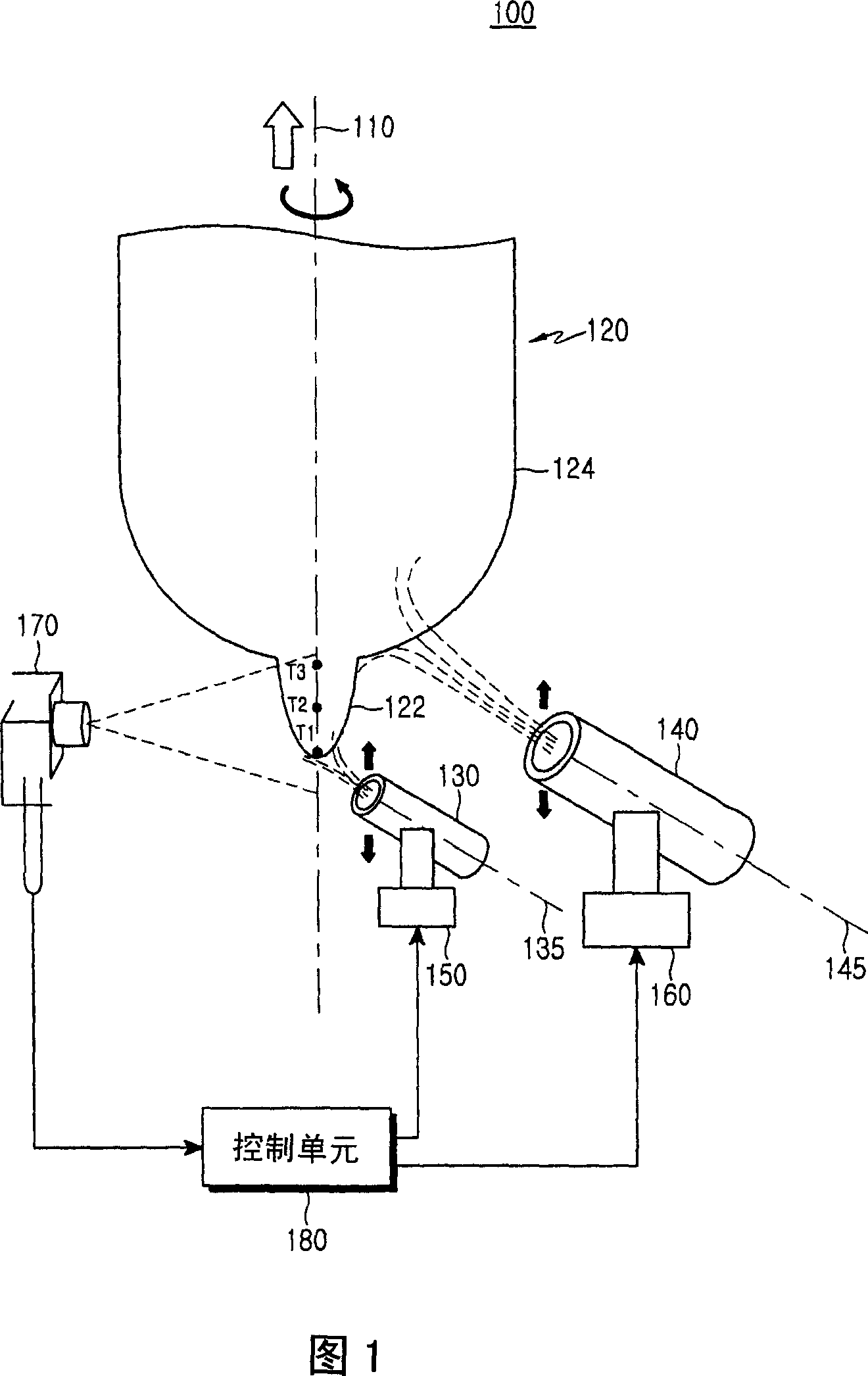
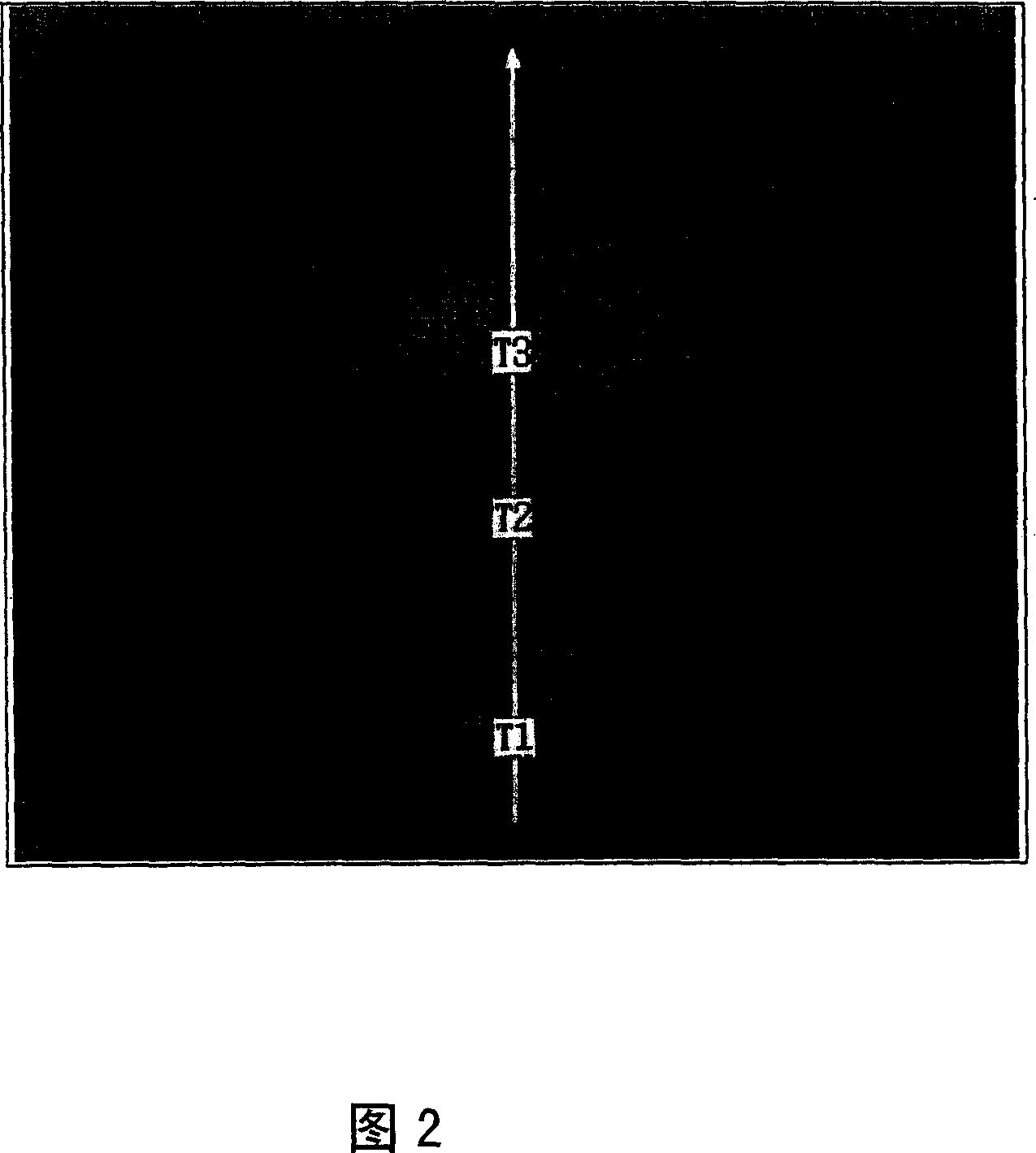
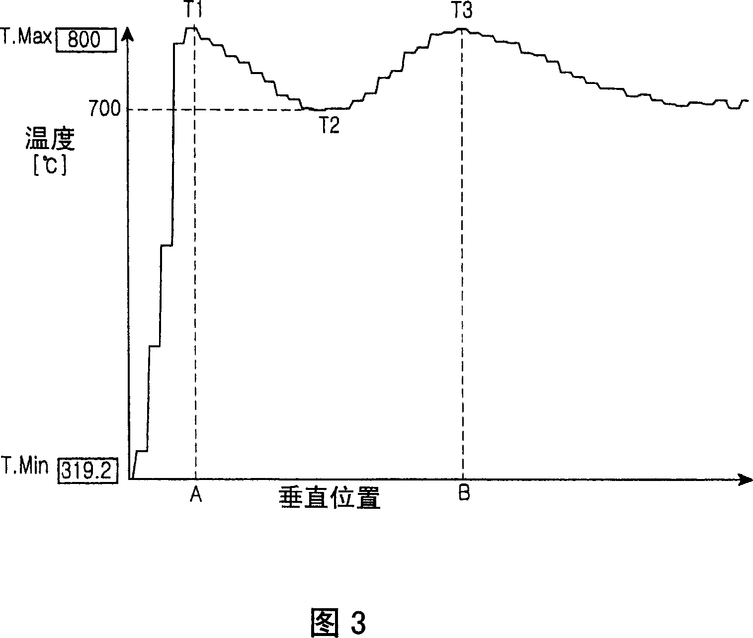
[0018] Fig. 1 illustrates a vapor phase axial deposition apparatus according to a preferred embodiment of the present invention. The vapor phase axial deposition apparatus 100 includes: first and second torches 130, 140 for generating and depositing soot; first and second tables 150, 160 for tilting the first and second torches, respectively; temperature measurement A unit 170, a temperature measuring unit 170 for detecting the temperature distribution of the end of the soot preform along the vertical axis ...


PUM


Abstract

Disclosed is a vapor axial deposition apparatus. The vapor axial deposition apparatus includes a first torch, a second torch, a temperature measuring unit and a controller unit. The first torch deposits soot on a distal end of a soot preform aligned with a vertical axis to thereby grow a core. The second torch deposits soot on an outer circumferential surface of the core to thereby grow a clad. The temperature measuring unit detects the temperature distribution of an end portion of the soot preform along the vertical axis. The controller unit determines first and second relative maximum temperatures T 1 and T 3, and relative minimum temperature T 2 between T 1 and T 3 in the detected temperature distribution, and controls T 1 to be within a predetermined range and the greater one of the difference (T 1 -T 2 ) and (T 3 -T 2 ) to not exceed a predetermined temperature.

Description

technical field [0001] The present invention relates to an apparatus and method for manufacturing an optical fiber preform, and more particularly, to a vapor axial deposition (VAD) apparatus and a vapor axial deposition method. Background technique [0002] The vapor-phase axial deposition method is a method of depositing soot on a starting rod made of glass material by using first and second torches to grow into a core and cladding in the longitudinal direction, thereby obtaining soot The preform method. Subsequently, the soot preform is subjected to a sintering process and the like to obtain an optical fiber preform. [0003] U.S. Patent No. 6,834,516 entitled "Manufacture of Optical Fiber Preform Using Improved VAD" and granted to Donald P. A vapor-phase axial deposition method for obtaining a soot preform with a uniform composition, in which an optical pyrometer is arranged together with a core torch. [0004] However, such a vapor phase axial deposition method has th...

Claims


Application Information

Patent Timeline
Patent Type & Authority Applications(China)
IPC IPC(8): C03B37/018
CPCC03B2207/66C03B2207/70C03B2207/64C03B37/0142Y02P40/57C03B37/018
Inventor 金镇杏李皓镇都文显成在铉金允镐
Owner SAMSUNG ELECTRONICS CO LTD
Why Eureka
Try Eureka