Method and device for reducing intake and exhaust resistance

A technology of intake and exhaust and resistance, which is applied in the direction of valve devices, engine components, machines/engines, etc., can solve the problems of inconvenient modification of internal combustion engines, and achieve the effect of improving performance and reducing intake and exhaust resistance

Inactive Publication Date: 2007-04-25
王洪泽
View PDF0 Cites 0 Cited by
  • Summary
  • Abstract
  • Description
  • Claims
  • Application Information

AI Technical Summary

Problems solved by technology

[0004] There are many inconveniences for users to modify the internal combustion engine

Method used


Image

  • Method and device for reducing intake and exhaust resistance
  • Method and device for reducing intake and exhaust resistance

Examples


Embodiment Construction

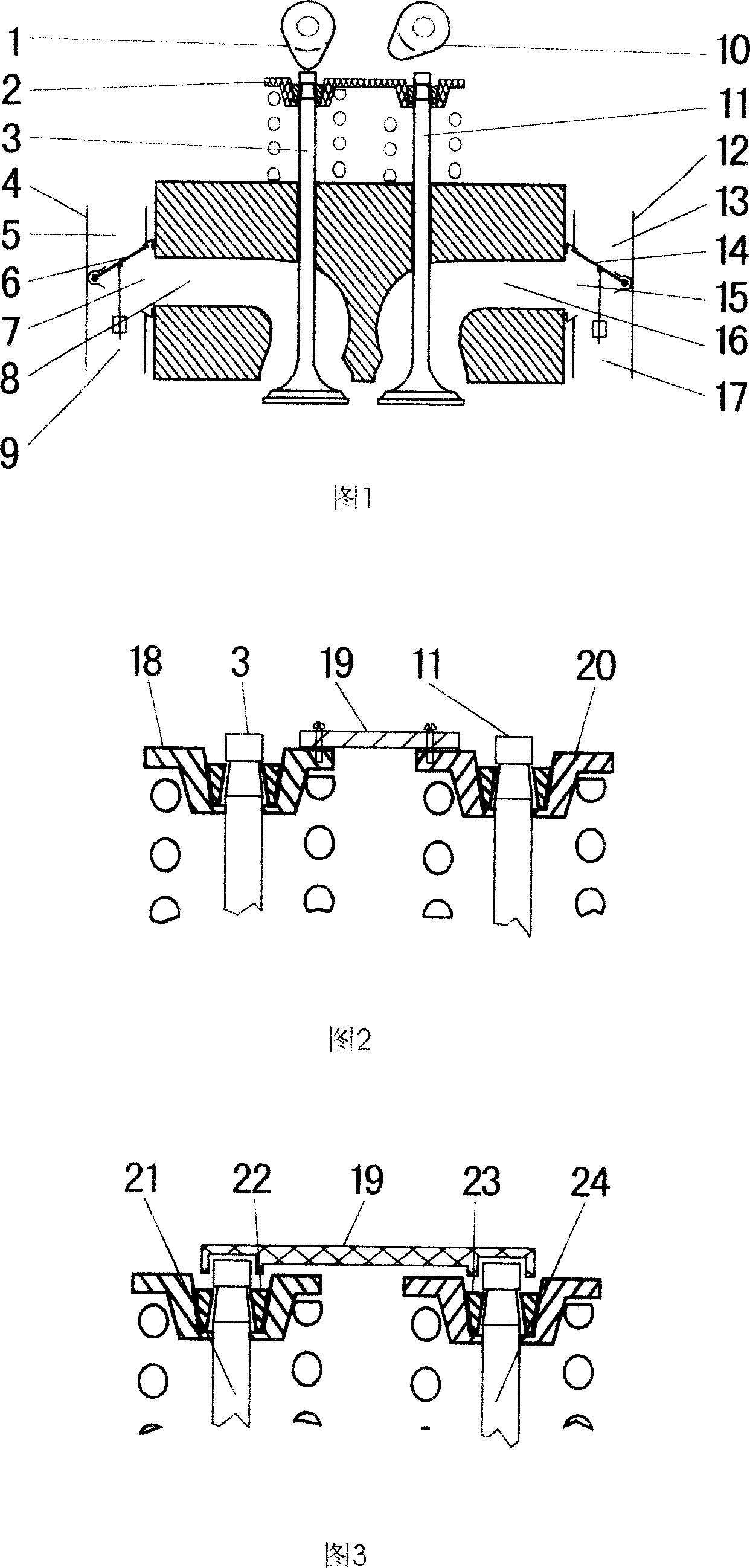
[0019] The present invention will be described below by taking two valves per cylinder as an example.

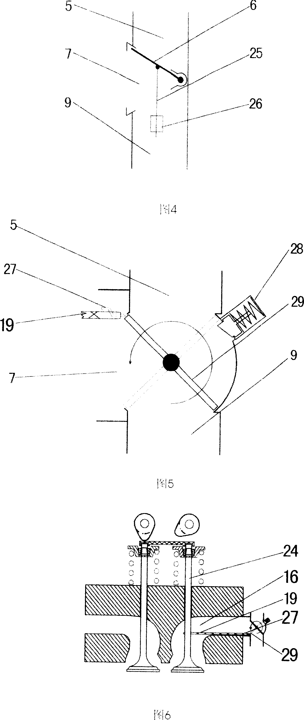
[0020] As shown in Figure 1 (the cylinder head is in the state of intake air), the valve spring seat (2) is integrated, the distribution valve (4) is installed on the intake port (8), and its intake and exhaust pipes (7) are connected to the intake port (8) communicate; distribution valve (12) device is on the exhaust passage (16), and its intake and exhaust pipe (15) communicates with exhaust passage (16).

[0021] When exhausting, the exhaust cam (10) opens the exhaust valve (11), and under the action of the integrated valve spring seat (2), the intake valve (3) also opens. The valve plate (6) and the valve plate (14) (respectively under the action of the following actuators, the same below) respectively close the intake manifold (9) and the intake manifold (17), and the exhaust manifold (5) and exhaust manifold (13) open. The exhaust gas is discharged through the intake...


PUM


Abstract

The invention provides a method for decreasing resistance of admission and exhaust and the equipment. Under no any change for gas engine the performance of gas engine is improved largely by lifting admission and exhaust door in the same time and increasing assignment action to admission and exhaust from assignment valve.

Description

technical field [0001] The invention relates to an internal combustion engine, in particular to a method and device for reducing intake and exhaust resistance. Background technique [0002] The higher the speed of the internal combustion engine, the more it is necessary to reduce the intake and exhaust resistance. [0003] Reducing intake and exhaust resistance is usually achieved by increasing the intake and exhaust flow area. [0004] There are many inconveniences for users to modify the internal combustion engine. Contents of the invention [0005] The invention provides an easy-to-implement method and device for reducing intake and exhaust resistance. [0006] The method to reduce the intake and exhaust resistance is: [0007] The intake and exhaust valves are opened and closed synchronously to increase the flow area of ​​the intake and exhaust; and the distribution valve is installed in the intake and exhaust passages to distribute the intake and exhaust, so that t...

Claims


Application Information

Patent Timeline
IPC IPC(8): F01L1/26
Inventor 王洪泽
Owner 王洪泽
Why Eureka
Try Eureka