Eureka AIR delivers breakthrough ideas for toughest innovation challenges, trusted by R&D personnel around the world.

General gasoline engine cylinder head cover

A general-purpose gasoline engine and cylinder head cover technology, which is applied to cylinder heads, cylinders, mechanical equipment, etc., can solve the problem that the breathing sheet sticks to the inner wall of the breathing sheet cover, affects the oil consumption and engine power, and affects the gas flow of the cylinder head cover, etc. problem, to achieve the effect of simple structure, improved power stability, and strong oil resistance

Inactive Publication Date: 2007-04-25
LONGXIN IND GROUP
View PDF0 Cites 4 Cited by
  • Summary
  • Abstract
  • Description
  • Claims
  • Application Information

AI Technical Summary

Problems solved by technology

The cylinder head cover with this structure has the following disadvantages: on the one hand, since the breathing piece is in a free state, it may move radially during its movement, resulting in a stagnation phenomenon, so that the breathing piece cannot be opened by positive pressure alone, making the breathing The port is in a normally closed state, resulting in excessive pressure in the crankcase and oil leakage from the oil seal.
At present, most general-purpose gasoline engine cylinder head covers use epoxy glass cloth laminates. After a general-purpose gasoline engine has been working for a period of time, a certain amount of waste oil will accumulate inside the cylinder head and on the breather, which will affect the cylinder head. gas flow rate, and it is easy to cause the breathing piece to stick to the inner wall of the breathing piece cover, so that the breathing piece cannot fall down only by the gravity and negative pressure of the breathing piece, and the breathing port is always open, which leads to the difference between the engine oil and the air in the crankcase A large amount of mixture enters the air filter, affecting oil consumption and engine power stability

Method used


Image

  • General gasoline engine cylinder head cover
  • General gasoline engine cylinder head cover

Examples


Embodiment Construction

[0012] The present invention will be further described below in conjunction with accompanying drawing.

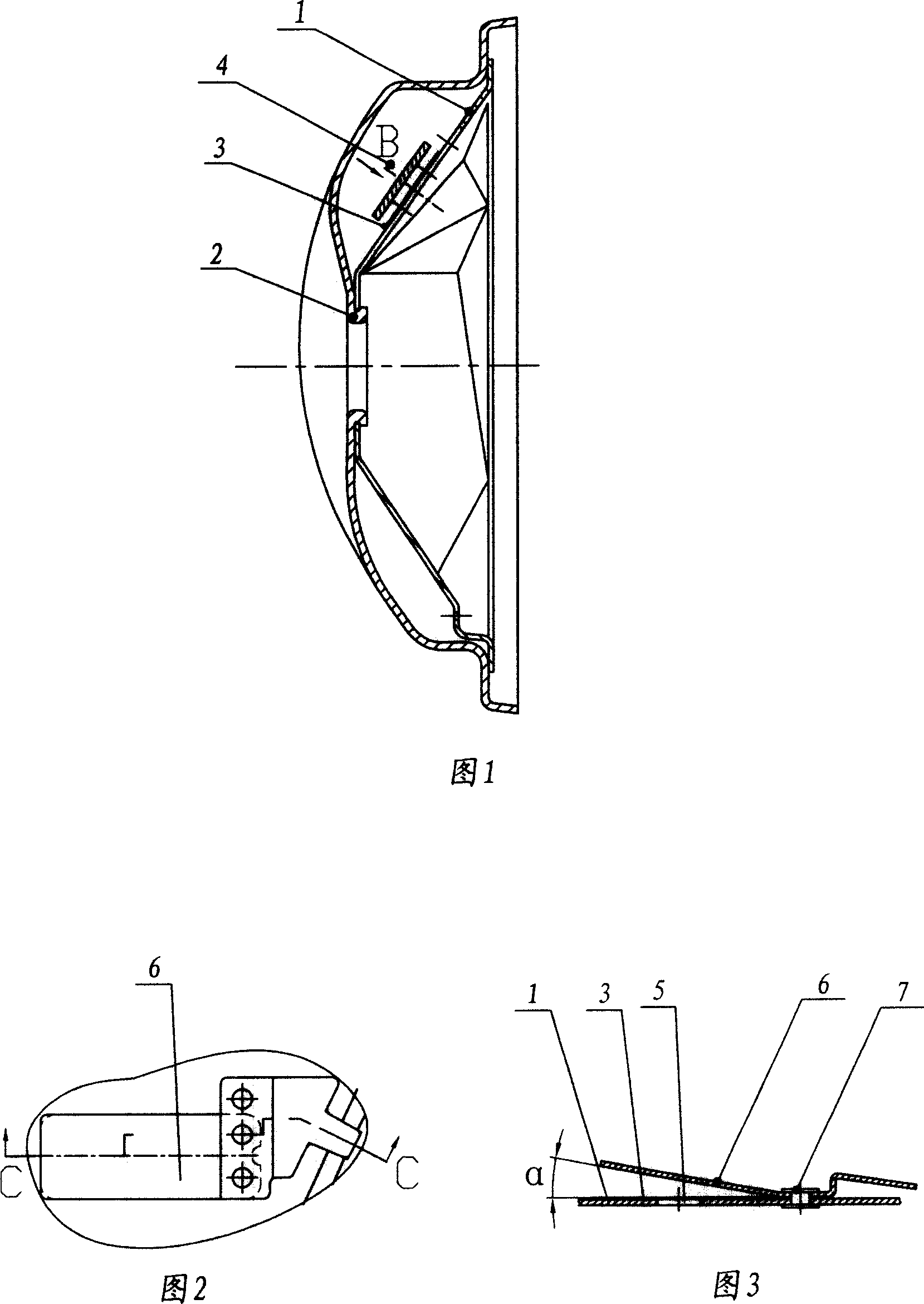
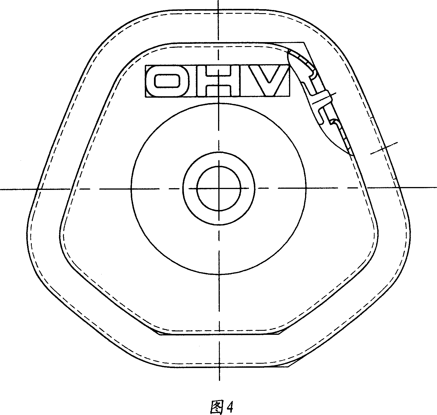
[0013] Referring to Fig. 1, Fig. 4, as can be seen from the figure, the general gasoline engine cylinder head cover of the present invention comprises cylinder head cover 1, cylinder head cover outer cover 2, breathing piece cover 6 and breathing piece 3, inner cover outer wall and outer cover A breathing chamber 4 is formed between the inner walls, and the breathing sheet cover 6 and the breathing sheet 3 are located in the breathing chamber 4, and a breathing port 5 connecting the crankcase with the breathing chamber 4 is provided on the inner cover 1 of the cylinder head cover. It is the same part as the prior art. Improvements of the present invention As can be seen from Fig. 1, Fig. 2 and Fig. 3, the breathing sheet 3 is attached to the outer wall of the inner cover to cover the breathing port 5, and the breathing sheet cover 6 is located on the breathing sheet 3, and ...


PUM


Abstract

The invention discloses a cylinder brainpan for common gas engine, comprising inner cover of cylinder brainpan, outer cover of cylinder brainpan, cover of breathing chip and breathing chip. Breathing cavity is formed between inside wall of inner cover and outside wall of outer cover, in which cover of breathing chip and breathing chip are set. Said breathing chip is spring steel chip. Breathing chip is pasted to the outside wall of inner cover so as to cover breathing port. The cover of breathing chip is set on the breathing chip and is fixed on the inner cover of cylinder brain span with the breathing chip. One end of the cover of breathing chip is upswept so as to form limiting angle where breathing chip swings at the angle range and the other end have an end face guiding exhaust pipe. Because breathing chip is spring steel chip and is fixed with inner cover, solving the problem of bonding and lagging of breathing chip in basic, avoiding often open and often close phenomenon entirely are realized. Stable working of the breathing chip ensures air flow smooth and achieves balancing the air press in crankcase efficiently.

Description

technical field [0001] The invention relates to parts of a general gasoline engine, in particular to a cylinder head cover of a general gasoline engine. Background technique [0002] The general-purpose gasoline engine cylinder head cover is generally formed by tightly pressing the inner cover of the cylinder head cover and the outer cover of the cylinder head cover. A breathing chamber is formed between the outer wall of the inner cover and the inner wall of the outer cover. The breathing chamber communicates with the atmosphere. There is a breather port communicating the crankcase with the breather chamber. Above the breathing port, there is a breathing sheet cover that guides the exhaust pipe, and a breathing sheet in a free state is arranged in the breathing chamber below the breathing sheet cover, and the rising stroke of the breathing sheet is limited by the breathing sheet cover. When the piston descends and the gas is compressed, the breathing piece opens under posi...

Claims


Application Information

Patent Timeline
Patent Type & Authority Applications(China)
IPC IPC(8): F01M13/00F02F1/24
Inventor 王虎山杨佺杜靖华
Owner LONGXIN IND GROUP
Why Eureka
Eureka Blog
Learn More