Adjacent induction device and its induction method

A technology of sensing device and sensing area, applied in the field of proximity sensing devices, can solve the problems of inability to popularize in large numbers, affecting the use effect, and false touch operation.

Inactive Publication Date: 2007-05-02
HOLTEK SEMICON
View PDF0 Cites 20 Cited by
  • Summary
  • Abstract
  • Description
  • Claims
  • Application Information

AI Technical Summary

Problems solved by technology

On the downside, frequent recalibration is required and performance is susceptible to wear and tear over time
The disadvantage is that fingers and stylus must be able to absorb sound waves, which are susceptible to noise interference. They have higher requirements for the power supply system and require a better screen surface cleanliness. Water stains or dirt will affect the use effect
[0010] In summary, the current working principles of proximity sensing devices can be classified into five categories: electric field, resistive, capacitive, acoustic, and optical. In actual use, the following difficulties are often encountered: (1) the design needs to be changed according to the installation environment, (2) the sensitivity will change with the environment, (3) it is difficult to avoid the same interference as the detection electrical , (4) Mis-touch operations often occur
Therefore, although touch and proximity sensors have been developed for a long time, they have not yet been widely adopted

Method used


Image

  • Adjacent induction device and its induction method
  • Adjacent induction device and its induction method
  • Adjacent induction device and its induction method

Examples


no. 1 approach

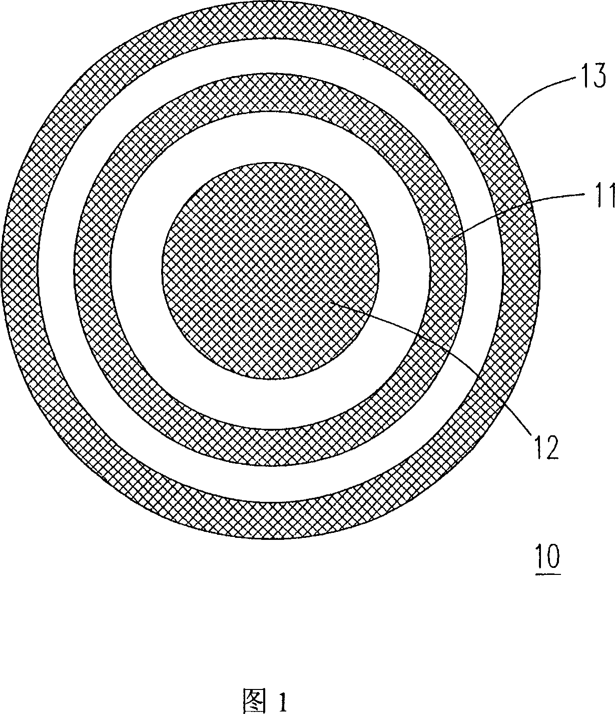
[0054] Please refer to FIG. 1 , which is a top view of a first embodiment of a proximity sensing device of the present invention. The proximity sensing device 10 in FIG. 1 includes a driving area 11 , an active area 12 and a restrictive area 13 . The first embodiment is an electric field proximity sensing device, wherein the drive area 11 is used to generate an electric field, and when the drive area 11 generates an electric field, both the sensing area 12 and the limited sensing area 13 will sense the base voltage, when there is no operation, the sensing area 12 and the limited sensing area 13 respectively sense the same voltage. The sensing area 12 is used for sensing operation and generates a first voltage change, and the sensing area 12 can also be regarded as a first sensing area. The limited sensing area 13 is used to sense the operation and generate a second voltage change, and the limited sensing area 13 can also be regarded as a second sensing area.

[0055] In the ...

no. 2 approach

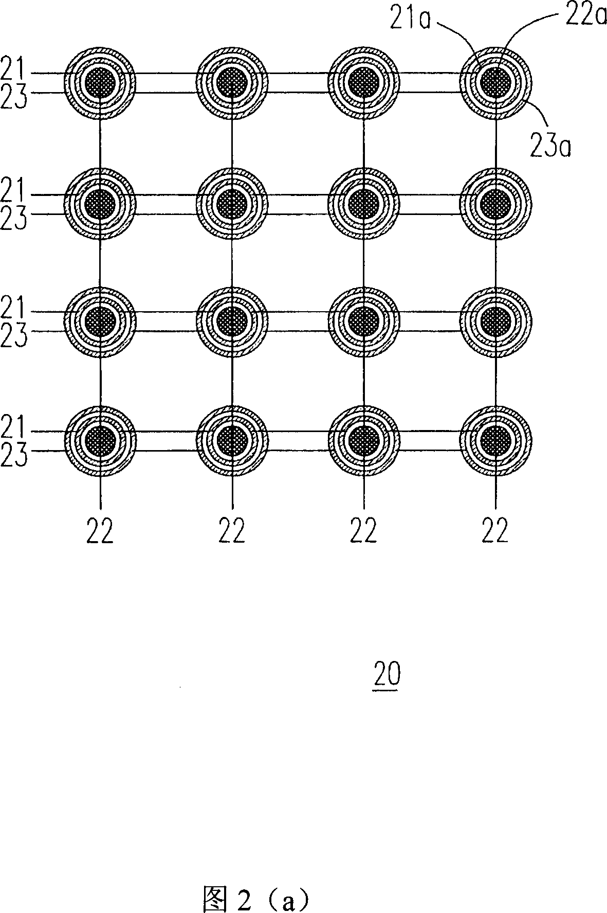
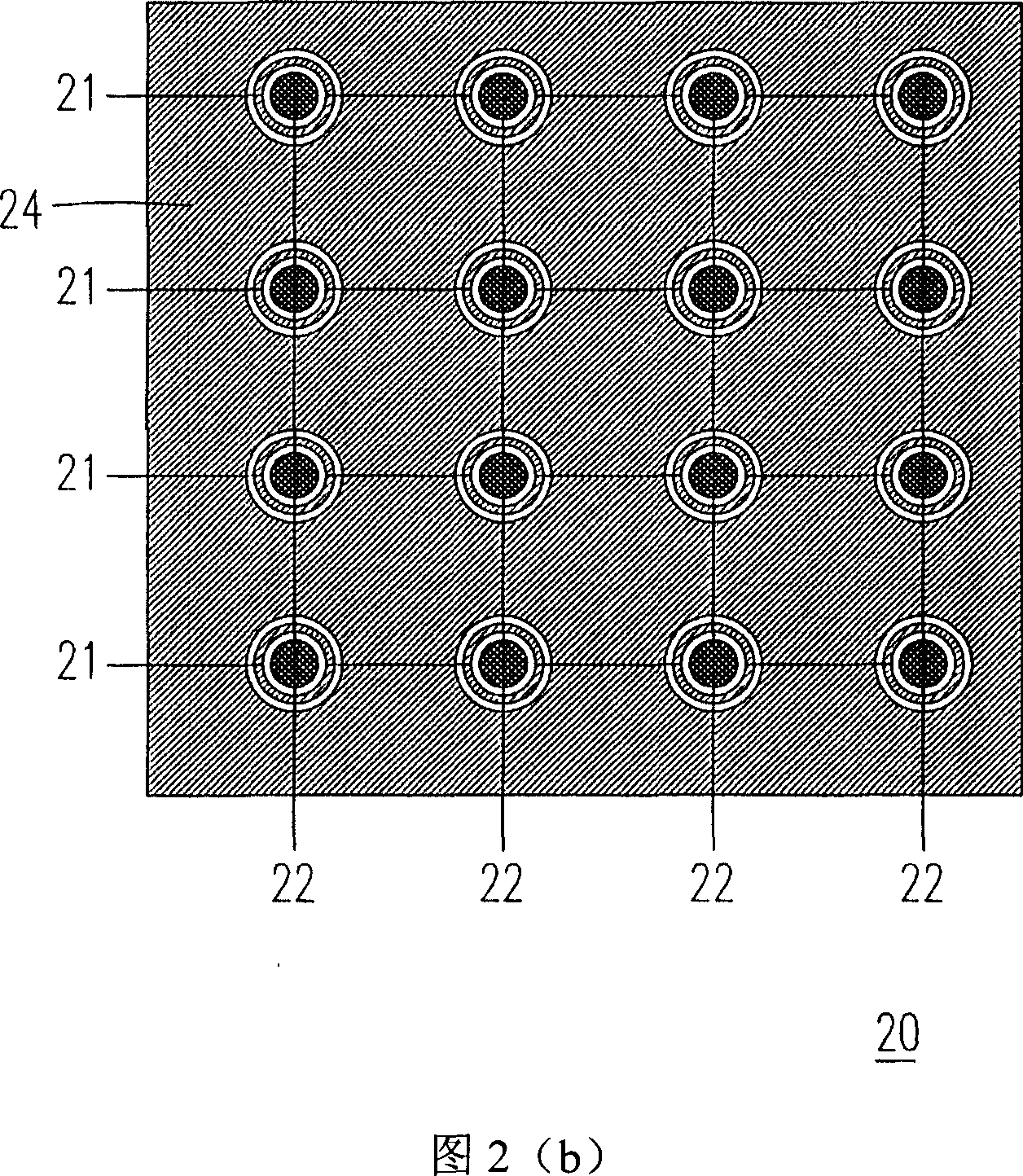
[0066] Please refer to FIG. 2( a ), which is a top view of a second embodiment of the proximity sensing device of the present invention. The proximity sensing device 20 in FIG. 2( a ) includes a plurality of driving regions 21 , a plurality of sensing regions 22 and a plurality of limiting sensing regions 23 . The second embodiment is an electric field proximity sensing device, wherein the plurality of driving regions 21 are used to generate an electric field. When the plurality of driving regions 21 generate an electric field, the plurality of sensing regions 22 and the plurality of limiting sensing regions 23 will induce a base voltage, and when there is no operation, the plurality of sensing regions 22 and the plurality of sensing regions 22 will Each of the restricted sensing regions 23 respectively senses the same voltage. The plurality of sensing regions 22 are used for sensing operation and generate a plurality of first voltage changes, and the plurality of sensing reg...

no. 3 approach

[0079] Please refer to FIG. 3 , which is a top view of a third embodiment of the proximity sensing device of the present invention. The proximity sensing device 30 in FIG. 3 includes a plurality of driving regions 31 , a sensing region 32 and a plurality of limiting sensing regions 33 . The third embodiment is an electric field proximity sensing device, wherein the plurality of driving regions 31 are used to generate an electric field. When the plurality of driving regions 31 generate an electric field, the sensing region 32 and the plurality of restricted sensing regions 33 will induce a basic voltage. When there is no operation, the sensing region 32 and the plurality of restricted sensing regions 33 respectively sense the same voltage magnitude. The sensing area 32 is used for sensing operation and generates a first voltage change, and the sensing area 32 can also be regarded as a first sensing area. The plurality of restricted sensing regions 33 are used for sensing oper...


PUM


Abstract

This invention puts forward an adjacent induction device used in judging if an operation is correct including a first induction region and a second induction region, in which, said first induction region is used in inducing the first operation signal generated by said operation, said second induction region is used in inducing the second signal generated by the operation, when ratio of the first operational signal to the second one is greater than the threshold value, said adjacent induction device judges said operation is correct.

Description

technical field [0001] The present invention refers to a switching device, in particular to a proximity sensing device of a switching device and a sensing method thereof. Background technique [0002] With the development of optoelectronic technology, the demand for proximity sensing switching devices is increasing. Common proximity switching devices include proximity switching switches and touch screens, etc., which are mainly used to switch system states. The operation mode of the proximity sensor is as follows: when an object is close to the sensing range of the sensor, the sensor senses the position of the object under the condition of touching the object or not touching the object, and the sensor and The sensed signal is converted into an electronic signal, and the system or machine will make an appropriate response according to the electronic signal to achieve the purpose of switching the system state. [0003] Taking the touch screen system as an example, it has a se...

Claims


Application Information

Patent Timeline
Patent Type & Authority Applications(China)
IPC IPC(8): H03K17/945H03K17/94H03K17/955
Inventor 陈俊雄
Owner HOLTEK SEMICON
Why Eureka
Try Eureka