
Carriageway-marking device and system

A roadway and light pipe technology, applied in the field of roadway marking devices and systems, can solve problems such as driver's dazzling, and achieve the effect of less maintenance and maintenance and long service life

Inactive Publication Date: 2007-05-02
3M INNOVATIVE PROPERTIES CO
View PDF2 Cites 3 Cited by
  • Summary
  • Abstract
  • Description
  • Claims
  • Application Information

AI Technical Summary

Problems solved by technology

Also, since the lights need to be mounted at a height comparable to the driver's head, the driver is dazzled, or at least disturbed by the glare, when a vehicle passes each light

Method used


Image

  • Carriageway-marking device and system
  • Carriageway-marking device and system
  • Carriageway-marking device and system

Examples


Embodiment Construction

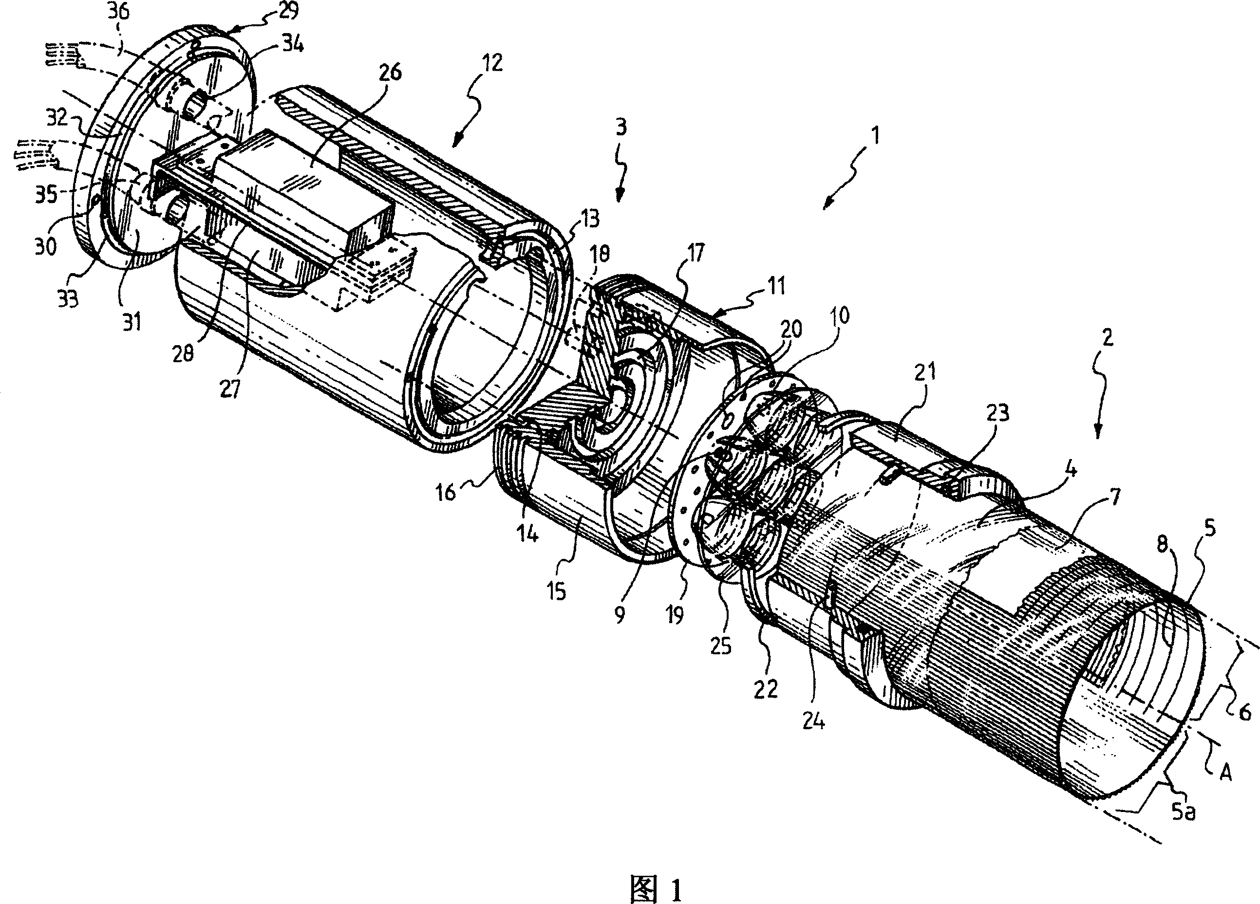
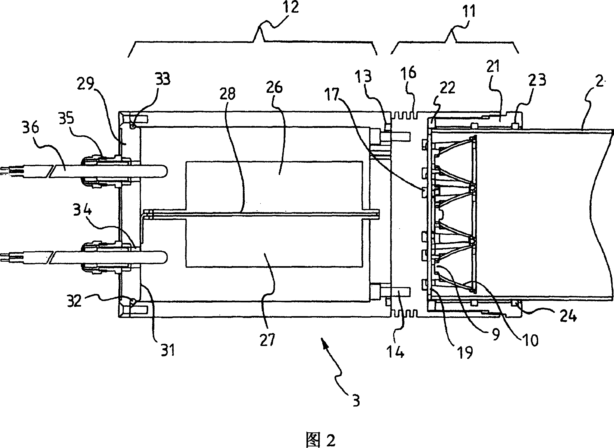
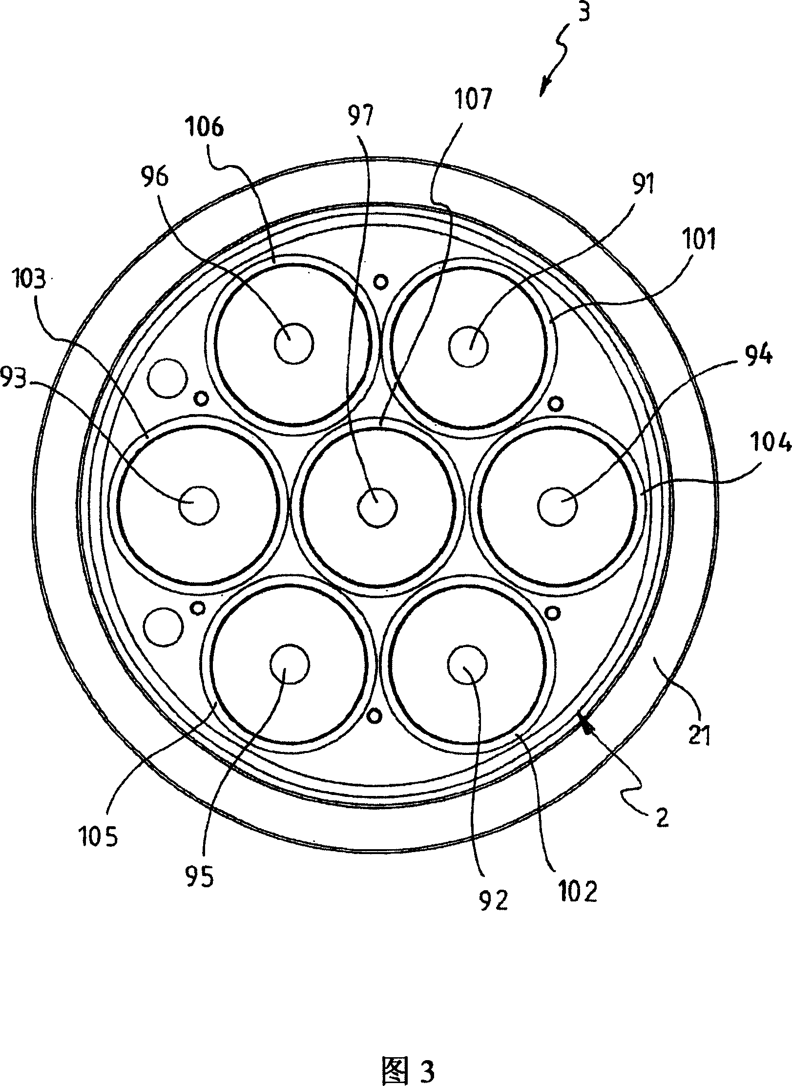
[0018] In the figures, a roadway marking device 1 is shown, which generally comprises a cylindrical light pipe 2 and a light projector 3 at one end of the light pipe 2 .

[0019] In a manner known per se, the light pipe 2 comprises a supporting transparent material 4 formed into a cylinder.

[0020] The supporting transparent material 4 is chosen to be flexible enough to allow bending according to the typical radius of curvature of the roadway. Coextruded polycarbonate and acrylic materials are suitable support transparent materials due to their suitable lifetime of at least ten years and suitable strength. The supporting transparent material 4 can also better resist ultraviolet rays.

[0021] The supporting transparent material 4 has a microstructured transparent material 5 as a lining. The microstructured transparent material 5 is more specifically arranged with its microstructures extending longitudinally and facing outwards.

[0022] A particularly suitable microstructu...


PUM


Abstract

A carriageway-marking device (1), comprising: a tubular light pipe (2) having a longitudinally extending light output window (5a) and a light extractor means (6); and a light projector (3) coupled to a first end of said light pipe (2) for projecting light thereinto, characterized in that said light projector (2) comprises a plurality of LEDs (9).

Description

technical field [0001] The invention relates to a lane marking device and system. Background technique [0002] In addition to the lines on the road, the edges of the roadway are usually marked by a series of spaced apart retroreflective elements, usually white on the outside of the vehicle and red on the inside of the vehicle. Since such elements only become visible when light from oncoming vehicles is incident, their performance is poor. At high speeds, sharp bends, slopes and similar situations, this can happen too late. Performance can become extremely poor in conditions of low visibility, especially due to fog. [0003] Lighting devices are also sometimes used, for example at deviations or dangerous bends. Lighting fixtures typically consist of a row of individual lights that can be lit continuously or flashed sequentially. In either case, a single lamp may only provide non-sequential marking. Furthermore, since the lamps need to be mounted at a comparable height t...

Claims


Application Information

Patent Timeline
IPC IPC(8): E01F9/00G02B6/00G08G1/09F21V8/00
CPCE01F9/002F21Y2103/00F21W2111/02F21Y2101/02G02B6/0096E01F9/20F21Y2115/10
Inventor 玛塞拉·M·佩森蒂
Owner 3M INNOVATIVE PROPERTIES CO
Features
  • Generate Ideas
  • Intellectual Property
  • Life Sciences
  • Materials
  • Tech Scout
  • Unparalleled Data Quality
  • Higher Quality Content
  • 60% Fewer Hallucinations
Learn More