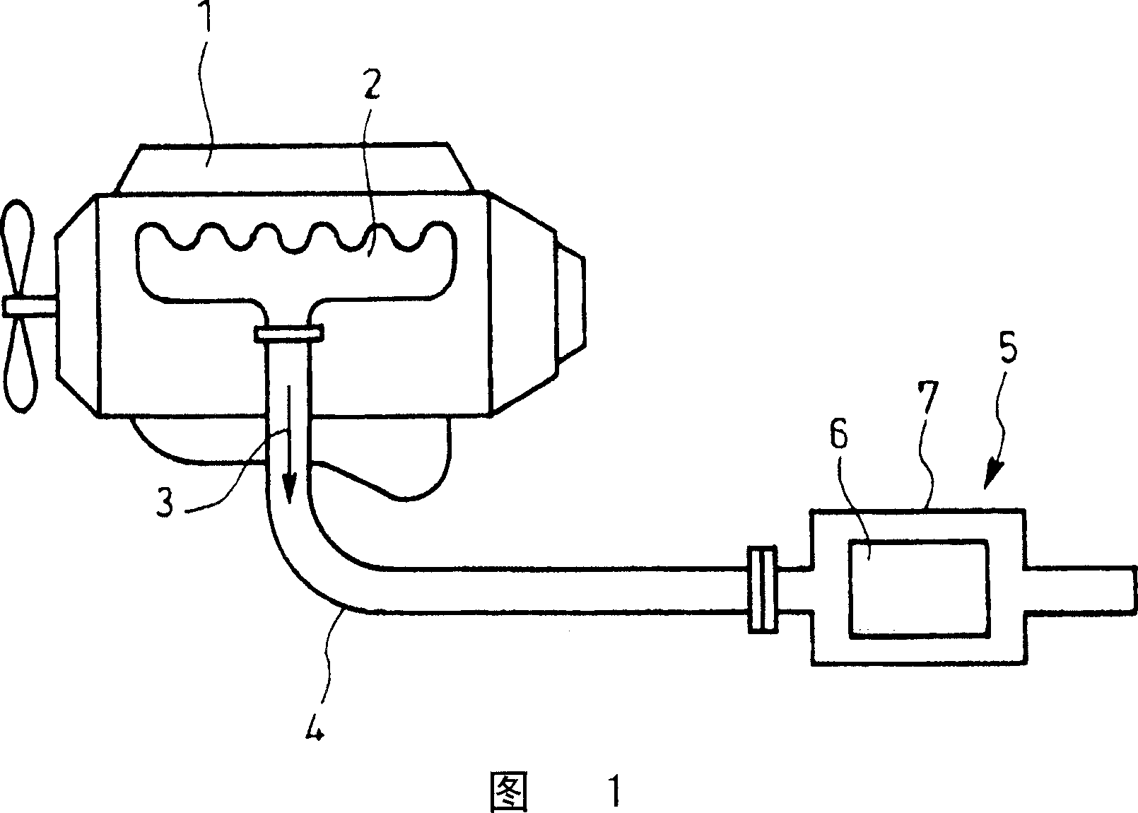
Exhaust gas purifier
A technology of exhaust purification device and temperature sensor, which is applied in the direction of exhaust device, noise reduction device, transportation and packaging, etc. It can solve the problem of low temperature measurement accuracy, no special consideration of the position of the detection element, and inability to accurately regenerate the particulate filter 6 Control and other issues, to achieve accurate regeneration control, improve the effect of temperature measurement accuracy
- Summary
- Abstract
- Description
- Claims
- Application Information
AI Technical Summary
Problems solved by technology
Method used
Image

Examples
Embodiment 1
[0045] FIGS. 7 and 8 are diagrams showing an embodiment of the present invention, and parts assigned the same reference numerals as those in FIGS. 1 to 6 denote the same members.
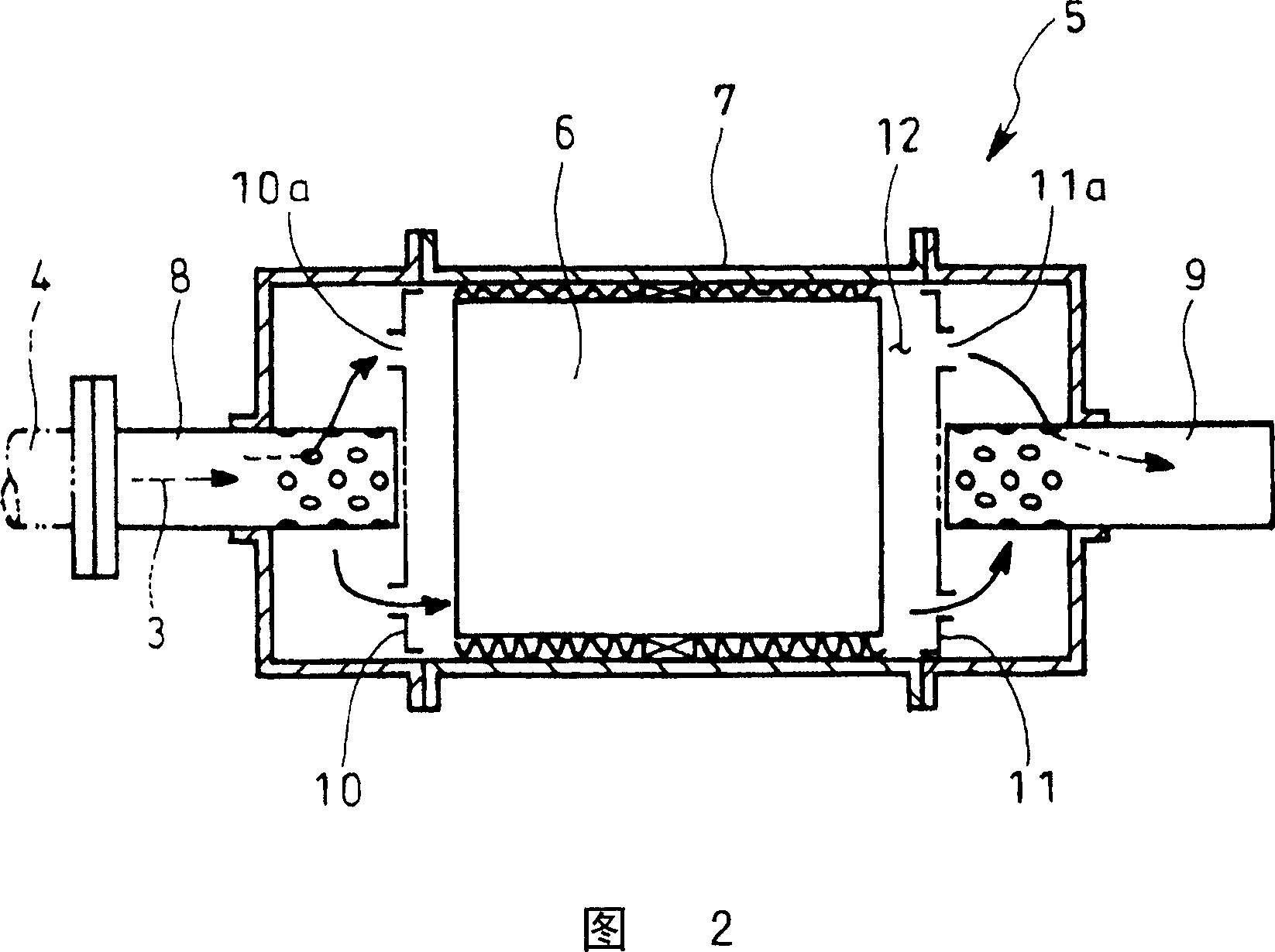
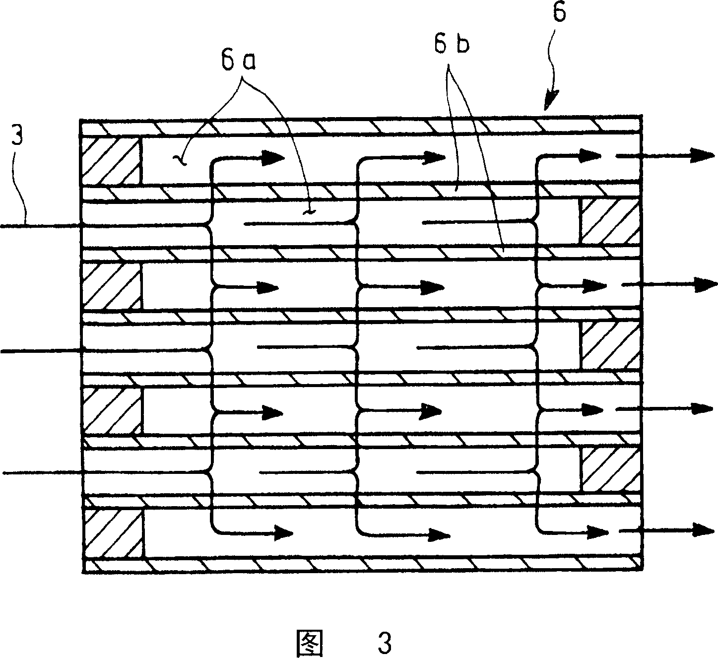
[0046] As shown in FIG. 7 , in this embodiment, in the filter case 7 sandwiched in the exhaust pipe 4, a pair of communication holes 10a, The distribution plates 10 and 11 of 11a house the catalyst regeneration type particulate filter 6 in the accommodation space 12 between these distribution plates 10 and 11, and the front stage of the particulate filter 6 in the storage space 12 Oxidation catalyst 13 is arranged at the place, and the position near the dispersion plate 10 of the entry side in the accommodation space 12, and the position of the dispersion plate 11 near the exit side in the accommodation space 12, and the oxidation catalyst 13 and the particle filter 6 mutually The detection element 15 of the temperature sensor 14 is respectively inserted at three positions between them.
[0047] Th...
Embodiment 2
[0053] In addition, FIG. 9 shows an example applied to diffuser plates 10, 11 of a form different from FIG. The inlet pipe 8 or the outlet pipe 9 is arranged eccentrically, and a plurality of relatively thin communication holes 10a, 11a are dispersedly provided around the connecting portion.
[0054] And the temperature sensor 14 of the position close to the distribution plate 10 of the entry side in the storage space 12, the detection element 15 is disposed directly behind the communication hole 10a larger than other openings on the distribution plate 10 of the entry side. Similarly, the temperature sensor 14 near the position of the outlet side dispersion plate 11 in the housing space 12 is arranged with the detection element 15 directly in front of the communication hole 11a which is larger than other openings on the outlet side dispersion plate 11, and is applied to such a form. In the case of the dispersing plates 10 and 11, the same effect as above can be achieved.
PUM
 Abstract
Description
Claims
Application Information
 - Generate Ideas
- Intellectual Property
- Life Sciences
- Materials
- Tech Scout
- Unparalleled Data Quality
- Higher Quality Content
- 60% Fewer Hallucinations
Browse by: Latest US Patents, China's latest patents, Technical Efficacy Thesaurus, Application Domain, Technology Topic, Popular Technical Reports.
© 2025 PatSnap. All rights reserved.Legal|Privacy policy|Modern Slavery Act Transparency Statement|Sitemap|About US| Contact US: help@patsnap.com