Vehicle bearing device

A technology for bearing devices and wheels, which is applied in the direction of bearings, axles, wheels, etc., can solve the problems of increased bearing torque, increased contact resistance, and increased wear of sealing lips, and achieve the effect of avoiding the number of components and avoiding complications

Inactive Publication Date: 2007-05-02
NTN CORP
View PDF1 Cites 13 Cited by
  • Summary
  • Abstract
  • Description
  • Claims
  • Application Information

AI Technical Summary

Problems solved by technology

In addition, since the seal lips 40a to 40c of the seal member 37 are brought into contact with the seal contact surface 32c of the inner member 32 with a predetermined interference, the contact resistance increases and the bearing torque increases.
In addition, the above-mentioned three sealing lips 40a-40c use the sealing contact surface 32c, that is, the hub wheel (hub axle) as the sliding surface, but since the sliding surface is constantly stained by muddy water, the sliding surface is prone to rust, and the result is The wear of the sealing lip increases, and if it is used for a long time, muddy water may penetrate into the bearing
In order to prevent muddy water from entering the inside of the bearing, it is considered to further increase the above-mentioned interference, but the contact resistance will be further increased, and the bearing torque will be further increased.

Method used


Image

  • Vehicle bearing device
  • Vehicle bearing device
  • Vehicle bearing device

Examples


Embodiment Construction

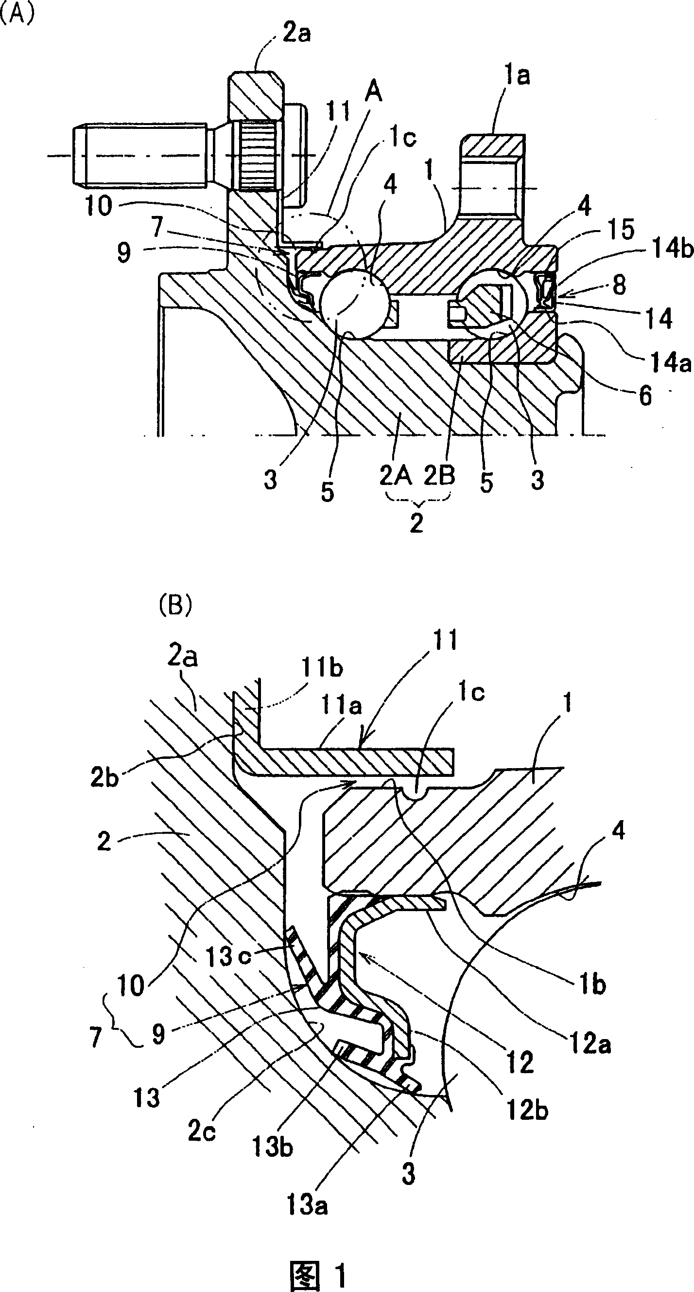
[0023] A first embodiment of the present invention will be described with reference to FIG. 1 . This embodiment is an inner wheel rotation type, a wheel bearing device for supporting a driven wheel, and is classified as a third-generation type. In addition, in this specification, in the assembled state of the vehicle, the side closer to the outer side in the vehicle width direction is called the outer side, and the side closer to the center in the vehicle width direction is called the inner side. In Fig. 1, the left side is the outer side, and the right side is the inner side.

[0024] This wheel bearing device includes: an outer member 1 having a plurality of rows of raceway surfaces 4 on the inner periphery; an inner member 2 having raceway surfaces 5 respectively facing these raceway surfaces 4; The multi-row rotating body 3. The rotors 3 are made of balls and are held by cages 6 for each row. This bearing device for a wheel is a multi-row angular contact ball bearing, t...


PUM


Abstract

Sealing structures (7, 8) are installed to seal opposite open ends of an annular bearing space between an outer member (1) and an inner member (2). A wheel mounting flange (2a) of the inner member (2) is provided with a shielding plate (11). The shielding plate (11) has a tubular wall (11a) forming a labyrinth seal (10) in the vicinity of an outer peripheral surface (1b) of an outboard end of the outer member (1). The outer peripheral surface (1b) is provided with a guide structure (1c) for guiding downwardly water, flowing in between the shielding plate (11) and the outer member (1) along the flange (2a) and the shielding plate (11), and water flowing in between the shielding plate (11) and the outer member (1) along the outer peripheral surface of the outer member (1). The guide structure (1c) is constituted by an annular groove or projection.

Description

technical field [0001] The present invention relates to a bearing device for a wheel in an automobile or the like, and particularly relates to a sealing structure thereof. Background technique [0002] Since the bearing devices used in vehicles such as motor vehicles are exposed to harsh environments such as road surfaces, it is required to reliably prevent the intrusion of dust or muddy water from the outside. The effect of preventing grease leakage. Therefore, for example, a sealing structure as shown in FIG. 9 is adopted (for example, JP-A-2003-202028). The bearing device of this figure is a device in which balls 33 are interposed between the multiple rows of raceway surfaces 34, 35 of the outer member 31 and the inner member 32, and the outer side of the annular space formed between the inner and outer members 32, 31 ( outboard) is sealed by a sealing member 37. The inboard end is sealed by a bearing cap (not shown) by pressing a slinger 38 into the outer diameter of ...

Claims


Application Information

Patent Timeline
Patent Type & Authority Applications(China)
IPC IPC(8): F16C33/80B60B35/18F16C19/18F16C33/60F16C33/76F16C33/78
CPCF16C19/186F16C33/58F16C2326/02F16C33/805F16C33/7876F16C33/7886F16C33/586
Inventor 鸟居晃石河智海铃木昭吾
Owner NTN CORP
Why Eureka
Try Eureka