Standing wave driven piezoelectric ceramic pump capable of realizing positive and negative directional flow of liquid
A piezoelectric ceramic pump and fluid flow technology, which is applied to pumps with flexible working elements, pumps, machines/engines, etc., can solve the problems of complex structure, traveling wave fluctuation of pump body, etc., achieve good results, reduce mechanical wear, The effect of easy operation
- Summary
- Abstract
- Description
- Claims
- Application Information
AI Technical Summary
Problems solved by technology
Method used
Image

Examples
Embodiment 1
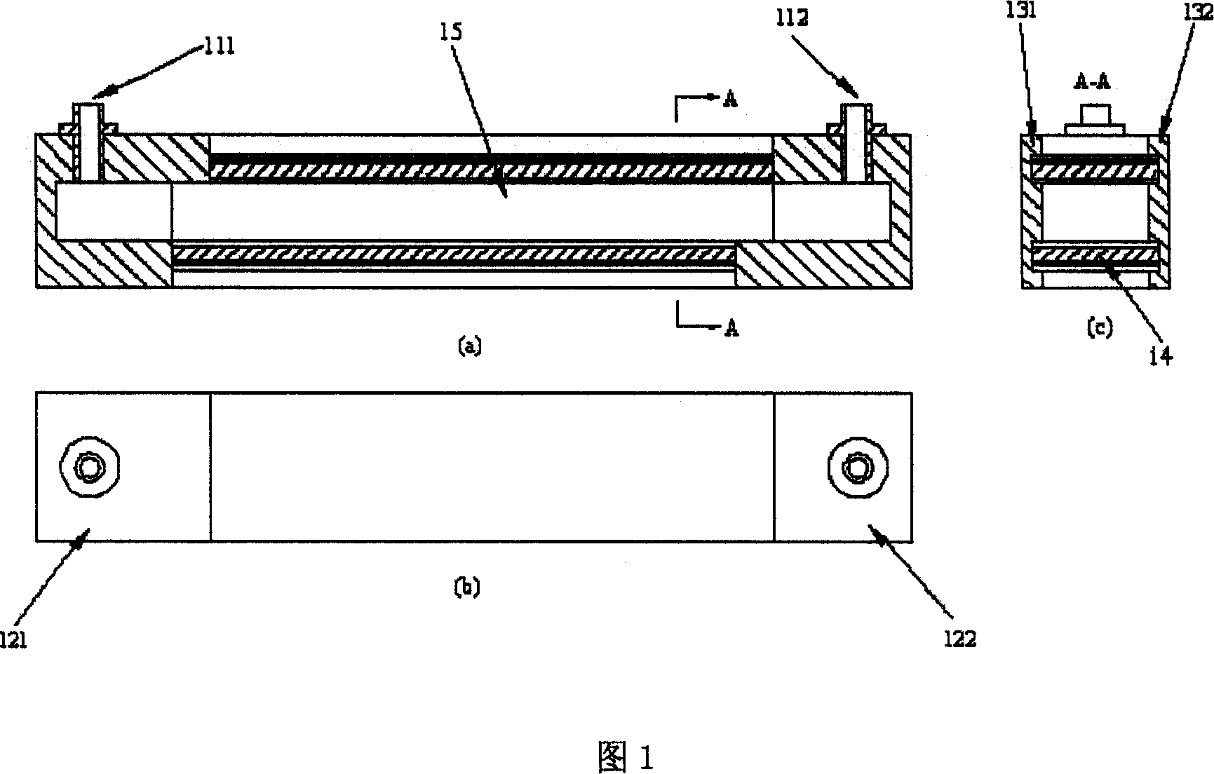
[0054] Embodiment 1: The present invention designs Embodiment 1 of a standing wave driven piezoelectric pump, as shown in FIG. 1 . In this embodiment, the standing wave driven piezoelectric pump consists of the inlet 111 (or 112 ) and the outlet 112 (or 111 ), the pump covers 121 and 122 , and the pump shells 131 and 132 bonded to each other. It is characterized in that two pairs of grooves are opened inside the pump casings 131 and 132, and the upper and lower piezoelectric vibrators 14 are embedded in them. The inlet and outlet are respectively fixed on the upper sides of the pump cover 121 and the pump cover 122 with glue. The pump cover 121 and the pump cover 122 are connected to the pump shells 131 and 132 with epoxy glue or AB glue. The pump cover, pump casing and inlet and outlet are all made of low-density lightweight materials such as fiberglass, nylon, or engineering plastics.
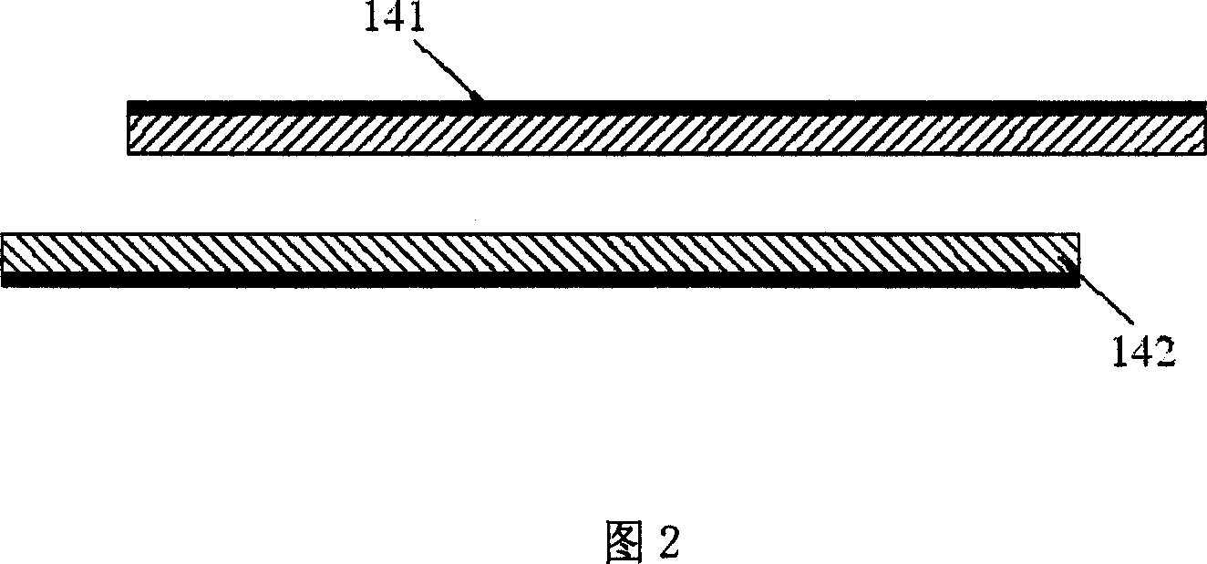
[0055] The piezoelectric vibrator 14 is formed by bonding the piezoelectric ceramic she...
Embodiment 2
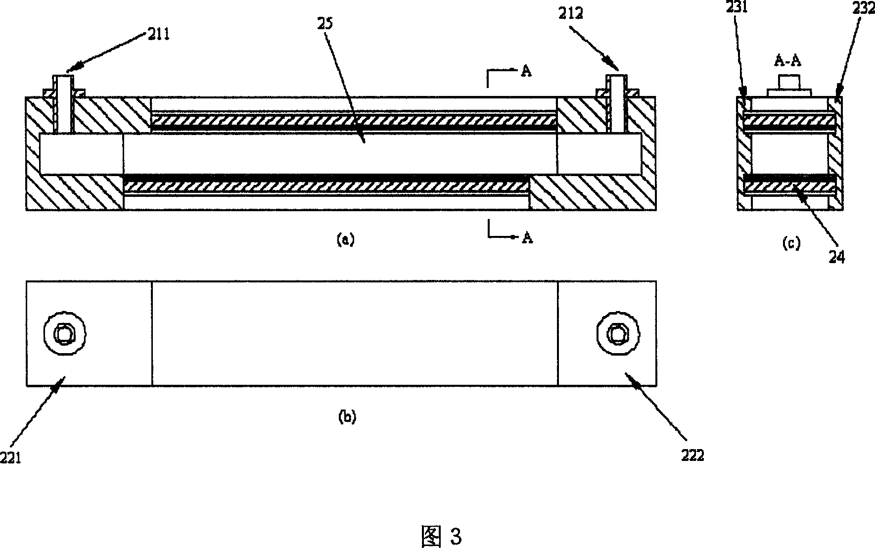
[0056] Embodiment 2: The present invention designs Embodiment 2 of a standing wave driven piezoelectric pump, as shown in FIG. 3 . In this embodiment, the standing wave driven piezoelectric pump consists of the inlet port 211 (or 212 ) and the outlet port 212 (or 211 ), the pump covers 221 and 222 , and the pump casings 231 and 232 bonded to each other. It is characterized in that two pairs of grooves are opened inside the pump casings 231 and 241, and the upper and lower piezoelectric vibrators 24 are embedded in them. The inlet and outlet are respectively fixed on the upper sides of the pump cover 221 and the pump cover 222 with glue. The pump cover 221 and the pump cover 222 are connected to the pump shells 232 and 232 with epoxy glue or AB glue. The pump cover, pump casing and inlet and outlet are all made of low-density lightweight materials such as fiberglass, nylon, or engineering plastics.
[0057] The piezoelectric vibrator 24 is formed by bonding the piezoelectric ...
Embodiment 3
[0058] Embodiment 3: The present invention designs a standing wave driven piezoelectric pump embodiment 3, as shown in FIG. 7 . In this embodiment, the piezoelectric pump driven by standing waves is composed of an inlet port 311 (or 312 ) and an outlet port 312 (or 311 ), pump covers 321 and 322 , and pump shells 331 and 332 bonded to each other. It is characterized in that three pairs of grooves are opened inside the pump casings 331 and 332, and the upper, middle and lower piezoelectric vibrators are respectively embedded in them. The inlet and outlet are respectively fixed on the pump cover 332 with glue. There is a boss in the middle of the pump cover 332, which is used to seal the pump cavity. The pump cover 321 and the pump cover 322 are connected to the pump shells 331 and 332 with epoxy glue or AB glue. The pump casing, pump body and inlet and outlet ports are all made of low-density lightweight materials such as fiberglass, nylon, or engineering plastics.
[0059] ...
PUM
 Abstract
Description
Claims
Application Information
 - R&D
- Intellectual Property
- Life Sciences
- Materials
- Tech Scout
- Unparalleled Data Quality
- Higher Quality Content
- 60% Fewer Hallucinations
Browse by: Latest US Patents, China's latest patents, Technical Efficacy Thesaurus, Application Domain, Technology Topic, Popular Technical Reports.
© 2025 PatSnap. All rights reserved.Legal|Privacy policy|Modern Slavery Act Transparency Statement|Sitemap|About US| Contact US: help@patsnap.com