Apparatus for pressurizing gas, liquid

A gas-liquid pressurization and hydraulic cylinder technology, which is applied in fluid pressure converters, mechanical equipment, etc., can solve the problem of reducing oil flow and achieve stable work, no cost, and small footprint

Inactive Publication Date: 2007-05-09
王彤
View PDF0 Cites 5 Cited by
  • Summary
  • Abstract
  • Description
  • Claims
  • Application Information

AI Technical Summary

Problems solved by technology

However, the commonly used pressurization technology is to push the large piston with air force, and use the small piston connected with it to push the

Method used


Image

  • Apparatus for pressurizing gas, liquid

Examples


Embodiment Construction

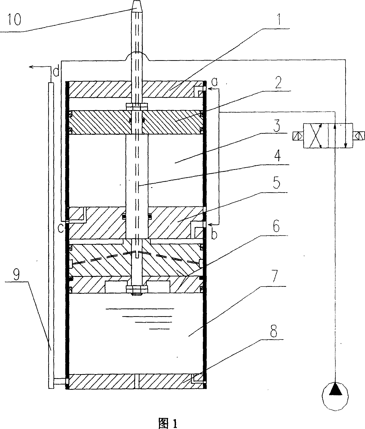
[0023] A gas-liquid supercharging device used in a hydraulic cylinder transmission system, which consists of a cylinder 7 and a piston 6, the piston 6 is set inside the cylinder 7, and a lower cylinder head 8 and a cylinder are respectively arranged at both ends of the cylinder 7 The cover 5, the cavity between the piston 6 and the lower cylinder cover 8 is an oil cavity, the cavity between the piston 6 and the cylinder cover 5 is an air cavity, and the lower cylinder cover 8 is provided with an oil outlet 9. The air inlet b of the air chamber is provided on the cover 5, which is characterized in that an upper cylinder 3 is provided on the cylinder head 5 and the cylinder head 5 is connected with one end of the upper cylinder 3, and the other end of the upper cylinder 3 There is an upper cylinder head 1, a cylinder piston 2 is arranged in the upper cylinder 3, an air inlet a is arranged on the upper cylinder head 1, and a breathing hole c which can communicate with the upper cy...


PUM


Abstract

A gas-liquid pressurizing device is prepared as setting piston in cylinder and setting bottom cylinder cover with oil outlet and cylinder cover with air inlet separately at two ends of cylinder, forming oil cavity by cavity between piston and bottom cylinder cover and forming air cavity by cavity between piston and cylinder cover, setting top cylinder on cylinder cover and connecting top cylinder to cylinder cover and top cylinder cover with breath hole and air inlet, arranging air cylinder piston in top cylinder, passing piston rod fixed on piston through cylinder cover then firm-jointing it with piston of air cylinder.

Description

technical field [0001] The invention relates to a supercharger, in particular to a gas-liquid supercharging device used in a hydraulic oil cylinder transmission system. Background technique [0002] Compared with hydraulic pressure, pneumatic has many advantages such as simple pipeline, convenient use and less investment, but the disadvantages of small thrust and large impact restrict its wide use. Pneumatic-hydraulic supercharged transmission can alleviate the above-mentioned shortcomings of pneumatics to a certain extent. However, the commonly used pressurization technology is to push the large piston with air force, and push the oil with the small piston connected with it. The disadvantage of this device is that the flow of oil is reduced, and it is suitable for occasions where the stroke of the oil cylinder is short. Contents of the invention [0003] The invention provides a gas-liquid supercharging device capable of increasing the output stroke of the working oil cy...

Claims


Application Information

Patent Timeline
IPC IPC(8): F15B3/00
Inventor 王彤
Owner 王彤
Why Eureka
Try Eureka