Coronal implanter in femoral head

A technology of implants and femoral heads, applied in joint implants, joint implants, physical therapy, etc., can solve the problem that the stimulation device cannot use the femoral head coronary system, and achieve long-term use

Inactive Publication Date: 2007-05-16
NEUE MAGNETODYN
View PDF2 Cites 27 Cited by
  • Summary
  • Abstract
  • Description
  • Claims
  • Application Information

AI Technical Summary

Problems solved by technology

[0005] Stimulation devices known to be used in combination with the types of hip prosthesis de...

Method used


Image

  • Coronal implanter in femoral head
  • Coronal implanter in femoral head

Examples


Embodiment Construction

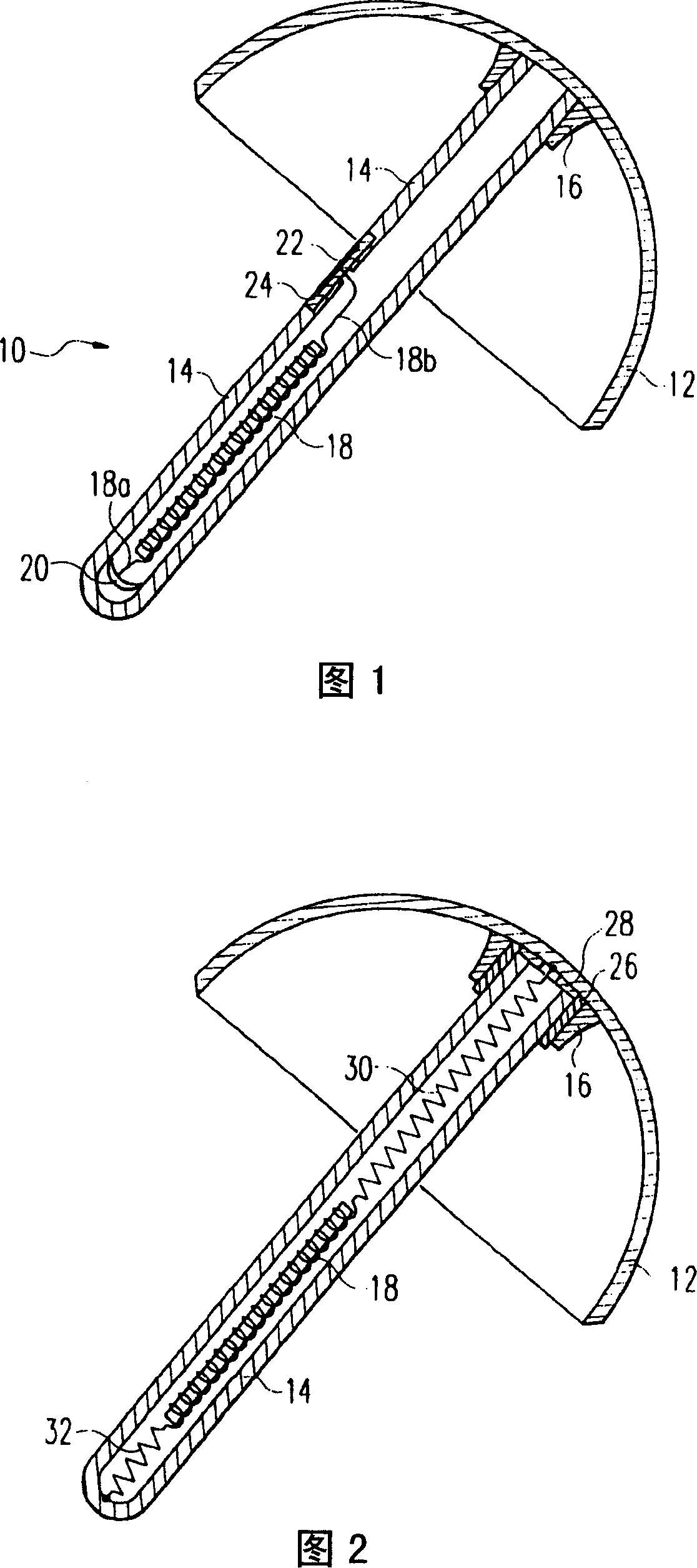
[0014] The femoral head crown implant 10 shown in FIG. 1 includes a cup-shaped crown member 12 and a rod-like rod or pin 14 . The pin 14 is connected to the crown member 12 by a tubular retainer 16 secured to the inner surface of the crown member 12 and receiving one end of the pin 14 . The pin 14 is inserted into a hole in the femoral neck bone such that the crown member 12 covers the surface of the corresponding pre-prepared hip joint head.

[0015] Crown member 12 and pin 14 comprise a histocompatible metal, particularly a cobalt-chromium-molybdenum alloy or a titanium-aluminum-vanadium alloy. To this extent, femoral head coronary prostheses are known from the above cited manuals.

[0016] In the embodiment of the invention shown in FIG. 1 , the pin 14 is a tube closed at its free end, inside which a coupling coil 18 is arranged. The coupling coil 18 has a rod-shaped magnetic core and a coil wound around it. One end 18a of the coupling coil 18 is electrically connected t...


PUM


Abstract

The invention relates to a femur crown implant (10), which comprises crow element (12) and the pin (14) fixed on the concave inner surface, wherein the couple winding (18) is inside the pin, while each end (18a, 18b) is connected to the organism electrode; one organism electrode is formed by crown element (12) while another one is formed by electrode (22); the electrode (22) is insulated with the pin or at least one part of pin. The invention uses external winding to generate low-frequency alternative-current in the couple winding (18), while said current will pass two organism electrodes into the femur of implant, to accelerate the activation of skeleton (as Kraus-Lechner).

Description

technical field [0001] The present invention relates to a femoral head crown implant, comprising a device capable of electrically stimulating the growth of bone tissue and maintaining its active condition. Background technique [0002] Low-frequency alternating current in the frequency range of about 8-20 Hz is known to promote tissue growth, especially bone growth (method according to Kraus-Lechner). Alternating current is applied through at least two tissue electrodes connected to the ends of an implanted coil ("pick-up coil"). Similar to a transformer, the alternating current in the coupling coil is induced by an external coil which is fed with a low-frequency alternating voltage via a suitable generator (DE-A-3132488). The present invention also uses this method. [0003] In order to stimulate bone growth and prevent loosening, hip rod prostheses are known (EP-A-0781432) in combination with coupling coils and tissue electrodes. [0004] A brochure from Midland Medical...

Claims


Application Information

Patent Timeline
IPC IPC(8): A61B17/56A61F2/32A61N1/36
Inventor 黑里贝特·斯特凡克里斯蒂安·克劳斯-冯·韦森杜克维尔纳·克劳斯
Owner NEUE MAGNETODYN
Why Eureka
Try Eureka