
Circuit breaker

一种功率开关、功率的技术,应用在电开关、高压/大电流开关、高压空气断路器等方向,能够解决费事成形、费事保持、昂贵等问题,达到高功率开关断开功率、提高可靠性的效果

Active Publication Date: 2007-05-16
HITACHI ENERGY LTD
View PDF1 Cites 8 Cited by
  • Summary
  • Abstract
  • Description
  • Claims
  • Application Information

AI Technical Summary

Problems solved by technology

[0003] The cooling device has cooling plates, which are complexly shaped to facilitate flow and must be held in place, and which are also made of a flame-resistant and therefore relatively expensive metal.

Method used


Image

  • Circuit breaker
  • Circuit breaker
  • Circuit breaker

Examples


Embodiment Construction

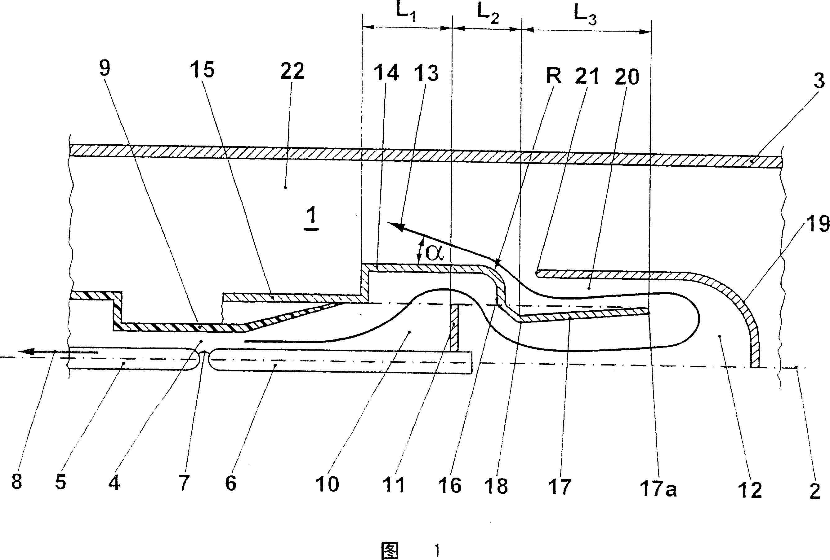
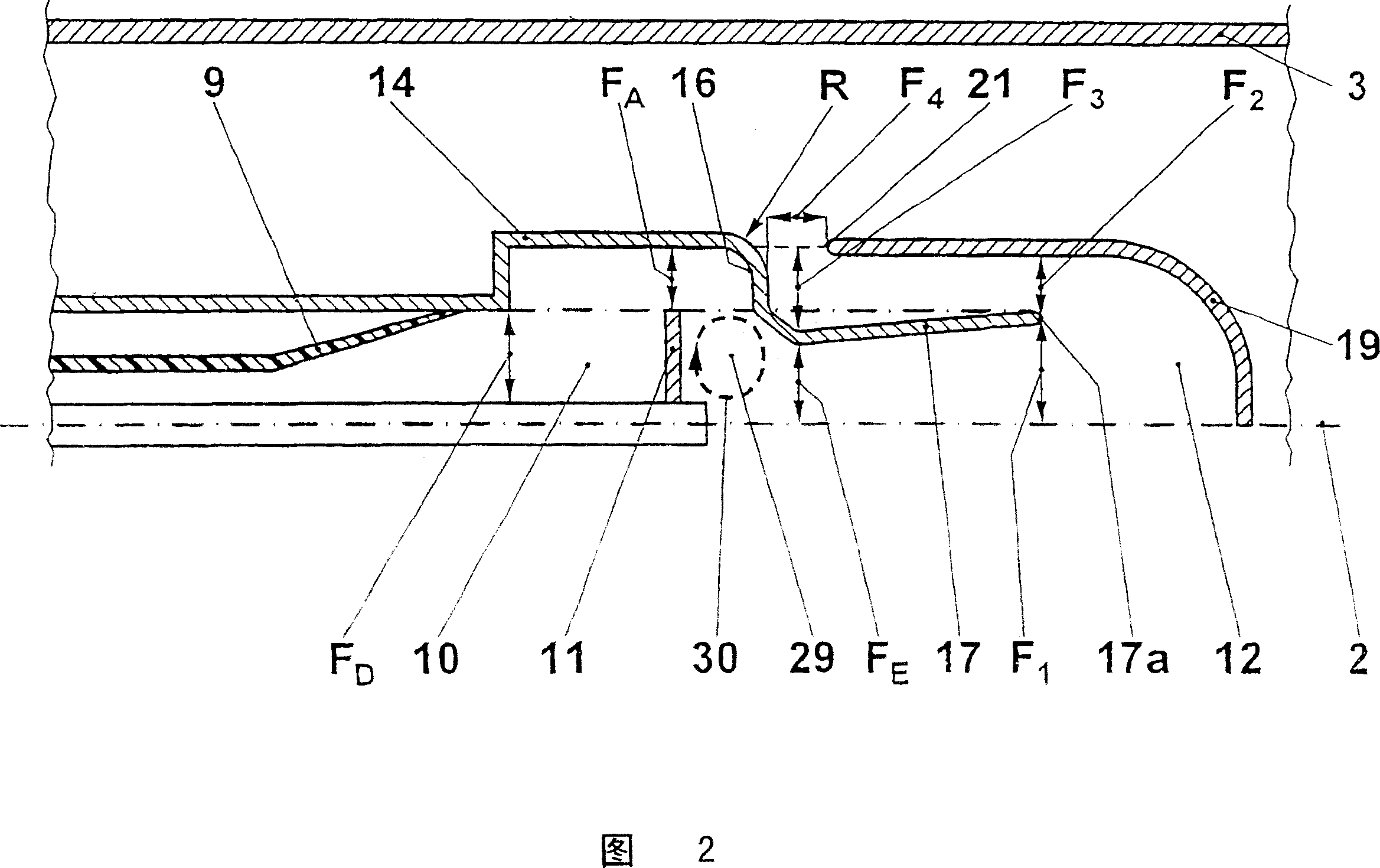
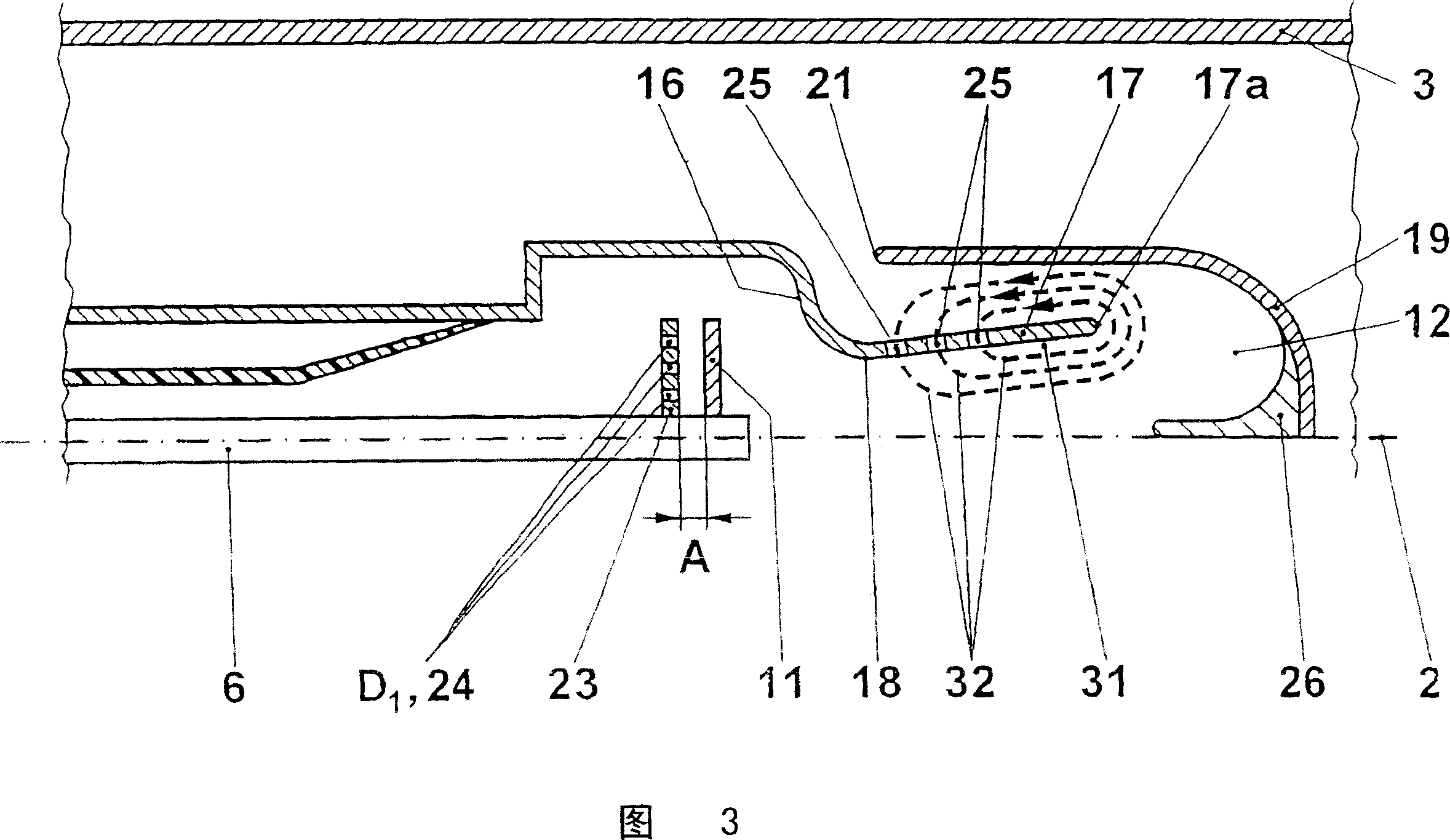
[0018] Elements with the same function are provided with the same reference symbols in all figures. All elements not necessary for a direct understanding of the invention are not shown and are not described.

[0019] A power switch can have one or more series-connected interrupters filled with insulating gas, which operate according to the conventional switching principle, that is, for example as an automatic blowing chamber, as an automatic blowing chamber with at least one additional compression piston arrangement Or as a simple compression piston switch. The power switch is formed as a covered power switch, wherein metal or plastic can be selected as the material of the cover. The power switch can also be an open-air switch, ie a part of a gas-insulated switchgear covered by a metal or a circuit breaker. FIG. 1 is a particularly simplified and schematically illustrated partial cross-sectional view of a first embodiment of a power switch during the switching-off process of...


PUM


Abstract

The invention relates to a power switch which comprises, encapsulated together with an insulating gas, at least one substantially radially symmetrical extinction chamber (1) filled with the insulating gas which extends along a longitudinal axis (2) and contains at least two power contacts (5, 6) and an arc quenching chamber (4) associated therewith. The arc quenching chamber (4) is functionally linked with at least one exhaust having an exhaust volume (12), which is adapted to cool the hot gases produced when the switch is switched off. The exhaust is linked with an arc quenching chamber volume (22). The aim of the invention is to substantially improve the arc quenching rate of power switches and to provide an exhaust which is comparatively simple and expensive in design. For this purpose, at least one forced recirculation area (29) increasing the flow resistance of the hot gases is provided in the area of the exhaust.

Description

technical field [0001] The invention relates to a power switch according to the preamble of claim 1 . Background technique [0002] A power switch is known from patent document CH 645 753, which can be used in a high-voltage network. This power switch has a rotationally symmetrical arc extinguishing chamber, which uses a negatively charged gas as an arc extinguishing and insulating medium, such as SF 6 full of gas. The quenching chamber has an arc chamber in which the quenching and insulating medium is ionized and heated by the breaking arc burning between the two power contacts. A part of the heated arc extinguishing and insulating medium is discharged through the insulating nozzle into the exhaust volume, where it is cooled by the cooling device and diverted. Mixing of the heated quenching and insulating medium with the cold gas present in the exhaust system can only be achieved to a relatively small extent, since the vast majority of the cold gas is quenched and insula...

Claims


Application Information

Patent Timeline
Patent Type & Authority Applications(China)
IPC IPC(8): H01H33/70
CPCH01H33/7015H01H2033/888
Inventor 叶向阳F·沃尔特H·海尔梅尔
Owner HITACHI ENERGY LTD
Learn More