

Wall plastering apparatus
A technology for plastering machines and walls, which is applied in the direction of construction and building construction, etc., can solve problems such as insufficient work efficiency, height limitation of fork-shaped plate group lifting, adverse effects of plaster plastering fastness, etc., so as to improve the plastering quality, The effect of high work efficiency and shortened construction period
- Summary
- Abstract
- Description
- Claims
- Application Information
AI Technical Summary
Problems solved by technology
Method used
Image

Examples
Embodiment Construction
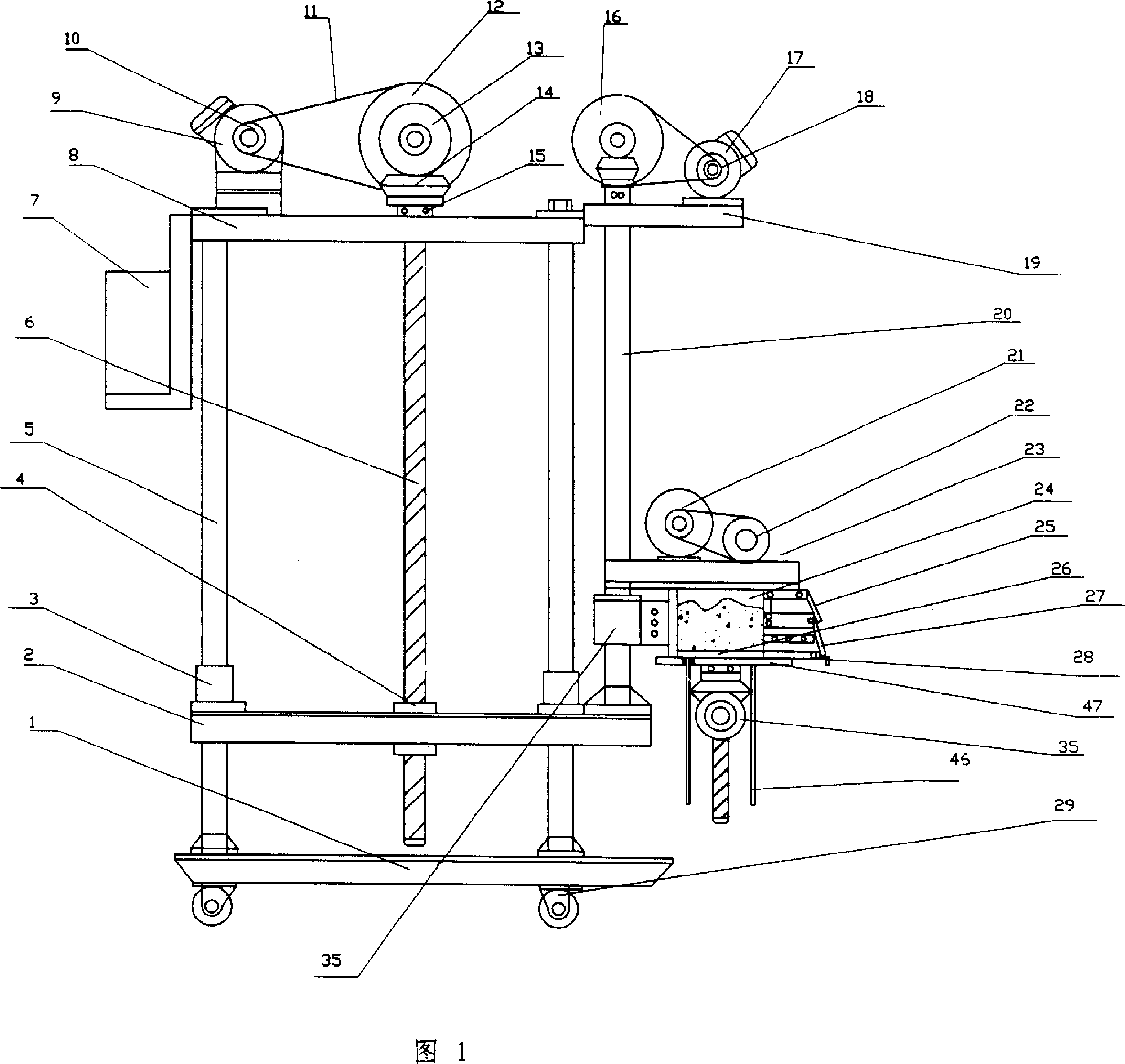
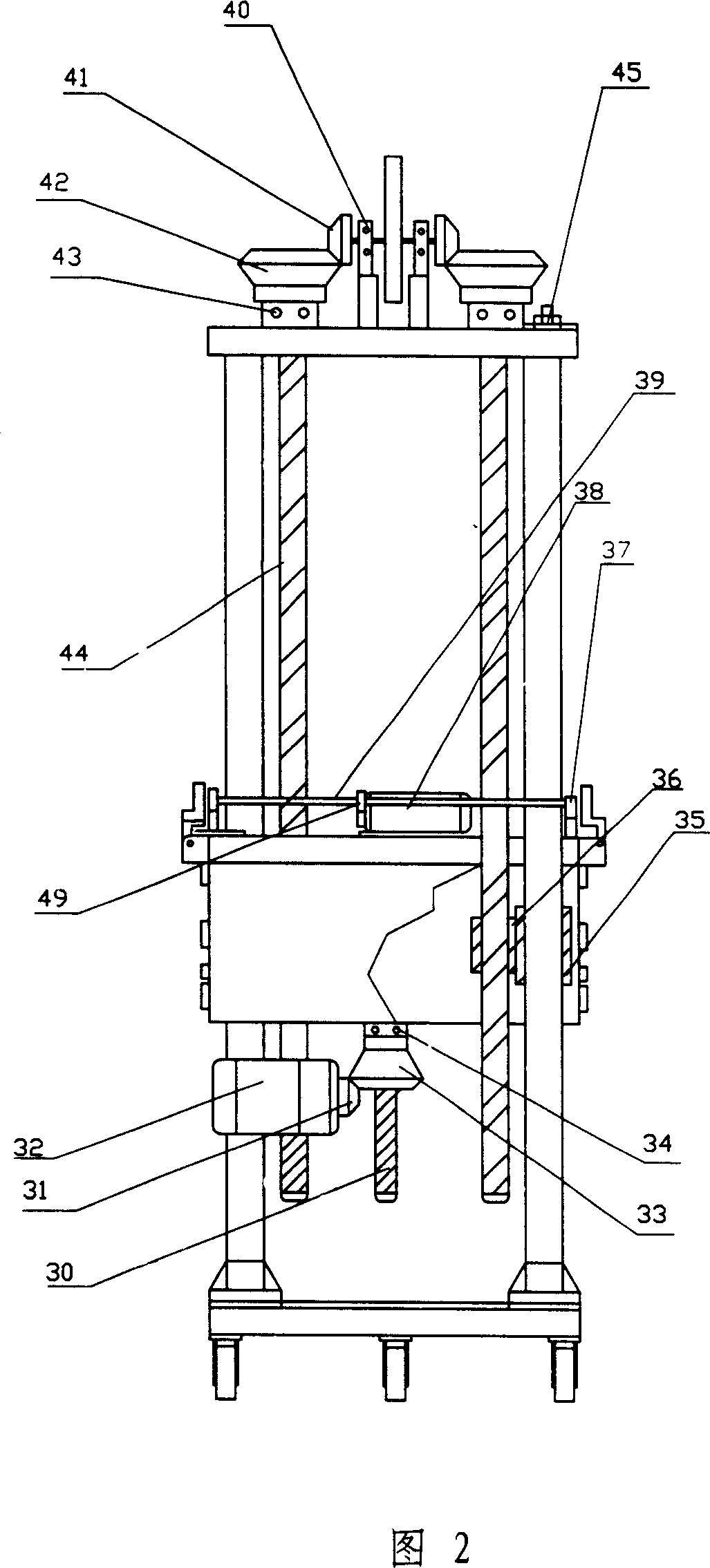
[0016] Referring to Fig. 1 and Fig. 2, a kind of wall plastering machine of the embodiment comprises a lifting device and a wall painting device, the lifting device is a two-stage elevating mechanism, and the primary elevating mechanism includes a bottom plate 1, a top plate 8, and four hard-coated surfaces. The fixed frame formed by the hollow column 5 of chromium, the lifting support 2 that can slide up and down the column 5 between the base plate 1 and the top plate 8, the lifting guide seat 3 is all provided at the passing position of the column 5 on the lifting support 2, To keep the balance of the lifting support 2; Gear 13 and bevel gear 14 are driven synchronously in the form of bevel gear transmission. The secondary lifting mechanism includes two hollow columns 20 with hard chrome plating on the upper plane edge of the lifting support 2, a small top plate 19 fixed on the column 20, and a small top plate 19 fixed on the small top plate 19 passing through and fixed on t...
PUM
 Abstract
Description
Claims
Application Information