
Control apparatus and method of flash memory

A control device and control method technology, applied in the field of flash memory control devices, can solve problems such as unavailable, large memory requirements, etc., and achieve the effect of avoiding the use of damaged blocks and reducing hardware costs

Inactive Publication Date: 2007-05-23
SUNPLUS TECH CO LTD
View PDF0 Cites 25 Cited by
  • Summary
  • Abstract
  • Description
  • Claims
  • Application Information

AI Technical Summary

Problems solved by technology

Such a large memory requirement cannot be provided on many embedded products

Method used


Image

  • Control apparatus and method of flash memory
  • Control apparatus and method of flash memory
  • Control apparatus and method of flash memory

Examples


Embodiment Construction

[0024] In order to make the above and other objects, features and advantages of the present invention more comprehensible, preferred embodiments will be described in detail below together with the accompanying drawings.

[0025] In order to prevent damaged blocks from being used by users, the previous technology uses the addresses of all storage blocks as a mapping table to exclude damaged blocks, which requires a lot of memory management and increases unnecessary hardware costs. . Therefore, the present invention proposes a flash memory control device and method, which can also achieve "preventing damaged blocks from being used by users" with a small amount of hardware cost. Detailed implementation will be described in the following examples.

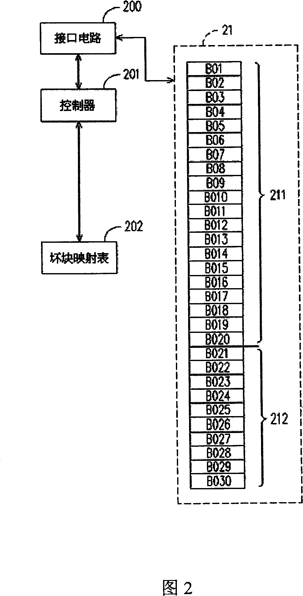
[0026] FIG. 2 is a circuit block diagram of a flash memory control device according to an embodiment of the present invention. Please refer to FIG. 2, the circuit block diagram of this embodiment includes an interface circuit 200, a ...


PUM


Abstract

A flash control device and method. The flash includes a number of flash memory blocks, in which these blocks are divided into a number of storage blocks, and several reserved blocks. This control device includes a bad block mapping table and a controller. When to access to the data by the block addresses, the controller judges whether the block corresponding to the block addresses is a damage block. When the controller determines the block corresponding to the block addresses is a damage block, it replaces the access block address to the corresponding reserved block address by finding the bad block mapping table. Next, the controller repeats the above operation until the reserved block corresponding to the access block address is the normal block, and access to data with the access block address.

Description

technical field [0001] The invention relates to storage equipment, in particular to a flash memory control device and method. Background technique [0002] With the popularity of consumer products, the demand for data storage is also increasing. As flash memory manufacturing technology has advanced by leaps and bounds, storage capacity has also increased day by day, and it is popular because of its small size and power-saving operation. However, the current semiconductor manufacturing process cannot guarantee that each storage block is well available when the flash memory leaves the factory. In addition, the number of times of writing and erasing of each storage block also has its own upper limit, and it will be damaged due to the end of its life in the process of use. Therefore, in order to develop a consumer product using a flash memory as a storage medium in the prior art, the control device of the flash memory must use a large memory to manage its storage space. [00...

Claims


Application Information

Patent Timeline
IPC IPC(8): G06F12/02G11C16/06
Inventor 陈泳成
Owner SUNPLUS TECH CO LTD
Learn More