Alignment device of out shaft of rotor axis of electric engine

A motor rotor shaft and straightening device technology, applied in the field of measurement, can solve the problems of instruments and control systems without automatic measurement, lack of adjustment of the position of the workpiece to be measured, and affect the stability of straightening accuracy, etc., to achieve simple structure and fast speed , the effect of convenient operation

Inactive Publication Date: 2007-05-23
SHANGHAI AEROSPACE AUTOMOBILE ELECTROMECHANICAL CO LTD
View PDF0 Cites 13 Cited by
  • Summary
  • Abstract
  • Description
  • Claims
  • Application Information

AI Technical Summary

Problems solved by technology

[0002] At present, the known straightening technology of the shaft end of the motor rotor shaft generally adopts manual methods and manual measurement. This kind of straightening device lacks an automatic driving device for adjusting the position of the workpiece to be measured and accurately straightening the force, and there is no automatic driving device combined with it. The measuring instrument and control system, the operator judges the alignment amount of the alignment point based on experience, and then performs multiple alignments by manual operation
This straightening method not only increases the labor intensity of the operator and reduces the production efficiency, but also affects the stability of the straightening accuracy due to human factors.

Method used


Image

  • Alignment device of out shaft of rotor axis of electric engine
  • Alignment device of out shaft of rotor axis of electric engine
  • Alignment device of out shaft of rotor axis of electric engine

Examples


Embodiment Construction

[0010] The present invention will be described in further detail below in conjunction with the accompanying drawings.

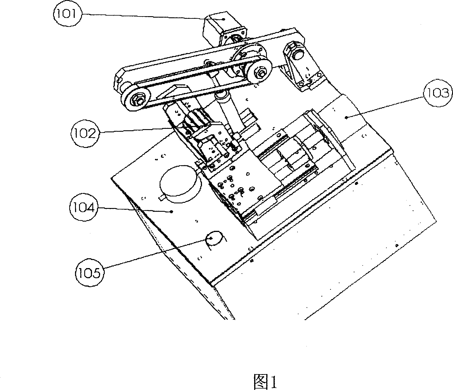
[0011] Fig. 1 is the structural diagram of the motor rotor shaft output shaft end straightening device of the present invention, comprising: a base plate 104, on which a roller driving device 101 is arranged for driving the motor rotor to be tested; the lower left side of the roller driving device 101 A finale detection fixture device 102 is provided for positioning and detecting the rotor of the motor to be tested; a straightening platform device 103 is provided on the front of the bottom plate 104 for realizing straightening and correction of workpieces; in the box under the bottom plate 104, install There are drivers and data communication devices for each motor, these drivers and data communication devices are connected with a computer and controlled by it; and process the data from the finale detection fixture device 102 to control the alignment of the to...


PUM


Abstract

The invention relates to an output axle corrector of motor rotor axle, which comprises a bottom plate with roller driver; the under left of roller driver has compressing checking clamper; the front of bottom plate has one correcting table; the box under the bottom plate has drivers of motors and data communicator, which are connected to one computer to be controlled to process the data of clamper, and control the table to correct the output axle. The invention has simple structure and high accuracy.

Description

technical field [0001] The invention relates to measuring technology, in particular to a measuring and straightening device for a motor rotor shaft output shaft end. Background technique [0002] At present, the known straightening technology of the shaft end of the motor rotor shaft generally adopts manual methods and manual measurement. This kind of straightening device lacks an automatic driving device for adjusting the position of the workpiece to be measured and accurately output force straightening, and there is no automatic driving device combined with it. For the measuring instrument and control system, the operator judges the alignment amount of the alignment point based on experience, and then performs multiple alignments by manual operation. This straightening method not only increases the labor intensity of the operator and reduces the production efficiency, but also affects the stability of straightening accuracy due to human factors. Contents of the invention...

Claims


Application Information

Patent Timeline
Patent Type & Authority Applications(China)
IPC IPC(8): H02K15/00B21D3/00
Inventor 李明符育刚殷沂柏郑会霖陈建康
Owner SHANGHAI AEROSPACE AUTOMOBILE ELECTROMECHANICAL CO LTD
Why Eureka
Try Eureka