
Backlight module frame preparation method

A backlight module and frame technology, applied in laser welding equipment, other manufacturing equipment/tools, optics, etc., can solve problems such as insufficient flatness of the joint surface, affecting the dimensional accuracy of the metal frame, and achieve the effect of reducing the cost of raw materials

Inactive Publication Date: 2007-05-30
HONG FU JIN PRECISION IND (SHENZHEN) CO LTD +1
View PDF0 Cites 14 Cited by
  • Summary
  • Abstract
  • Description
  • Claims
  • Application Information

AI Technical Summary

Problems solved by technology

Although this kind of preparation method can reduce the generation of waste materials, this preparation method will lead to insufficient flatness of the joint surfaces of the multiple frame units, which will seriously affect the dimensional accuracy of the metal frame.

Method used


Image

  • Backlight module frame preparation method
  • Backlight module frame preparation method
  • Backlight module frame preparation method

Examples


Embodiment Construction

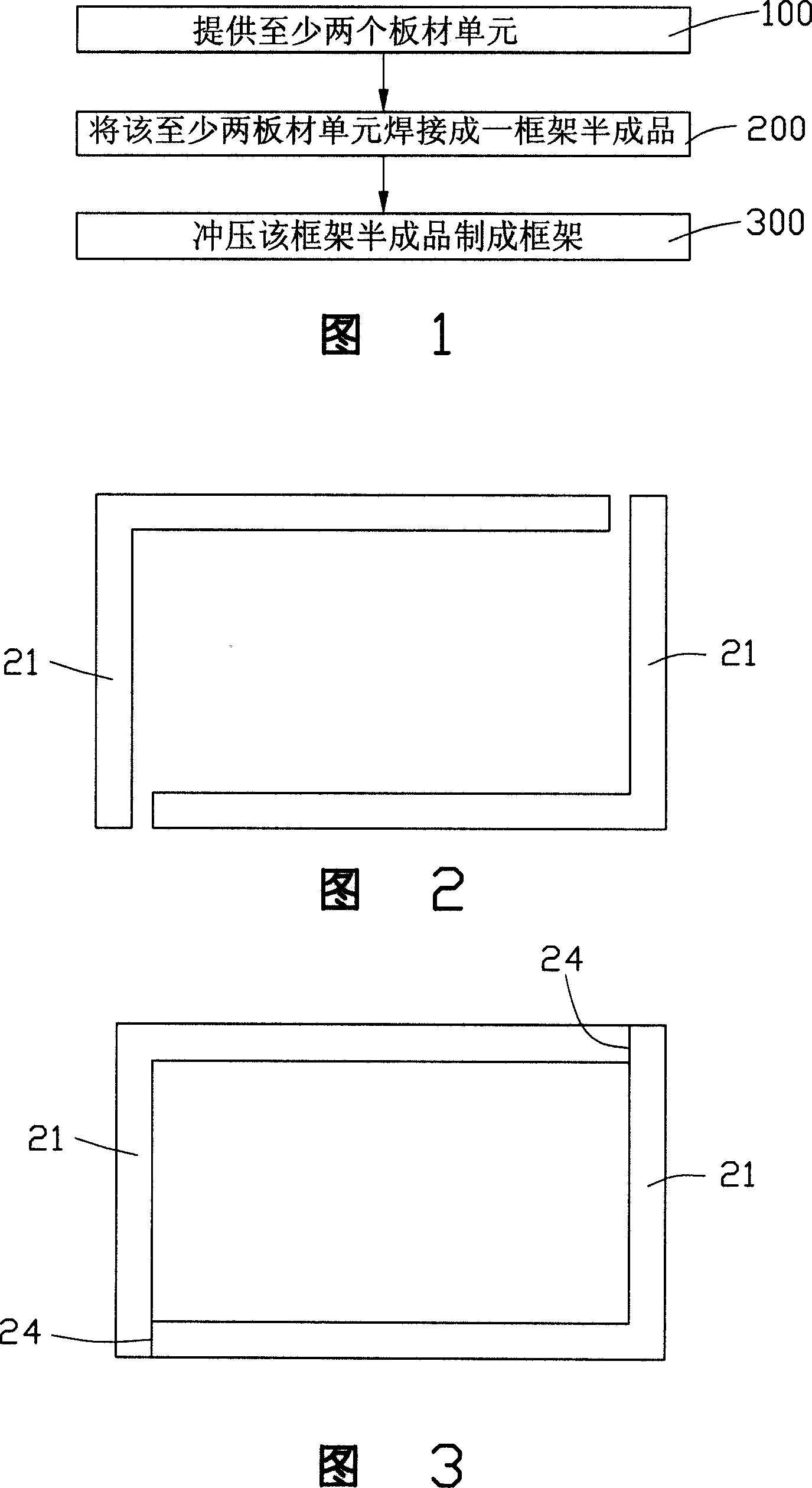
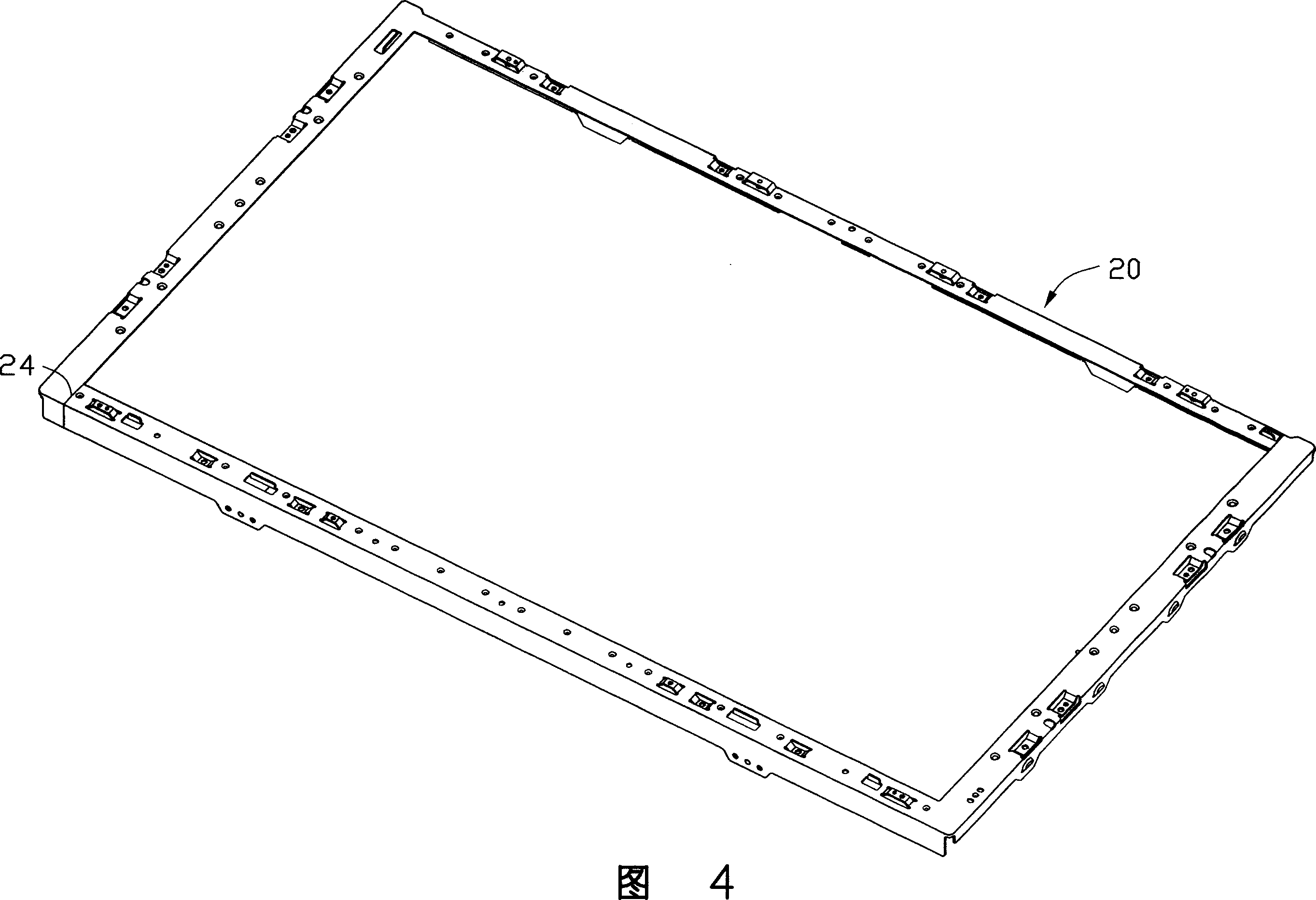
[0017] Referring to FIG. 1, the present invention provides a method for preparing a backlight module frame, which includes the following steps:

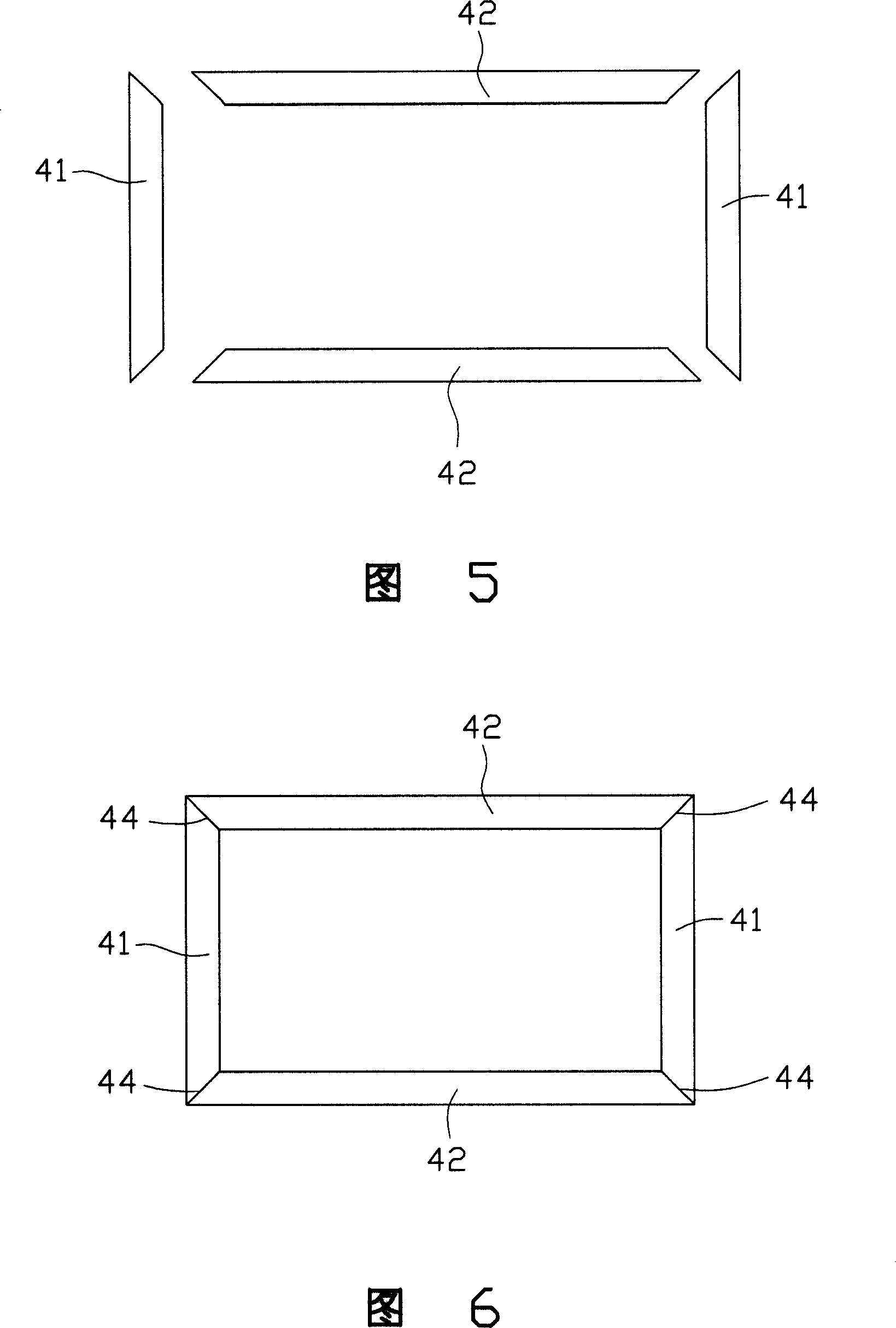
[0018] Step 100 is to provide at least two plate units. The outer shape of the plate unit can be long or L-shaped, which can be formed by cutting metal plates by a punch. The plate unit is made of metal material. The multiple plate units can be spliced ​​into a frame shape, and the width and length of the plate units are slightly larger than those of the designed frame. The main purpose is to consider the appropriate area required for the subsequent stamping steps. In addition, in order to increase the joint strength of the subsequent welding, the ends of the plurality of plate units can be arranged inclined.

[0019] Step 200 is to weld the at least two plate units into a frame semi-finished product. The edges of the plurality of plate units to be welded are in flush contact, and then at least one laser beam is used to weld the joints o...


PUM


Abstract

The aphototropism mould train frame has at least two plate units, welding the plates into a frame or semi finished part, stamping the semi product to a frame. It can improve the material availability ratio while ensuring the flatness of the overall frame.

Description

【Technical Field】 [0001] The invention relates to a method for preparing a backlight module frame applied to a liquid crystal display device. 【Background technique】 [0002] Because of the advantages of lightness, thinness, and low power consumption, liquid crystal displays are widely used in modern information equipment such as notebook computers, mobile phones, and personal digital assistants. Because the liquid crystal in the liquid crystal display does not have light-emitting characteristics, in order to achieve the display effect, it is necessary to provide a surface light source device for the liquid crystal display panel, such as a backlight module, whose function is to provide the liquid crystal display panel with a surface light source with sufficient brightness and uniform distribution. [0003] The backlight module generally includes a light source, an optical sheet, and a metal frame for accommodating and fixing the aforementioned elements. The optical sheet generally...

Claims


Application Information

Patent Timeline
Patent Type & Authority Applications(China)
IPC IPC(8): B23P23/04B23K26/20
CPCG02F1/133608
Inventor 许东明
Owner HONG FU JIN PRECISION IND (SHENZHEN) CO LTD
Learn More