
Insulating shield and conductive rod assembly

A technology of insulating shield and conducting rod, applied in the direction of insulated cables, insulated conductors, insulators, etc., can solve the unsatisfactory performance of anti-creepage and anti-sparking, affect the reliable operation of electrical equipment, and increase the design and manufacturing workload. and other problems, to achieve the effect of good protection and electrical insulation, ingenious design and simple manufacturing process

Inactive Publication Date: 2007-05-30
ZHEJIANG DONGYA ELECTROMECHANICAL
View PDF1 Cites 3 Cited by
  • Summary
  • Abstract
  • Description
  • Claims
  • Application Information

AI Technical Summary

Problems solved by technology

As the paper bushing is easy to be affected by moisture, the dielectric loss of the bushing will increase and the insulation strength will decrease, which will affect the reliable operation of electrical equipment
At the same time, when the paper casing is repaired after being damp, even if it is dried for 72 hours, it is difficult to completely restore the required technical indicators, which adds a lot of workload to the actual operating unit
[0005] Chinese patent document CN2356408Y discloses a composite insulated conductive rod assembly for high-voltage electrical appliances, including a conductive rod and an insulating sleeve sleeved outside the conductive rod. The sleeve is a composite structure, and the inner layer is composed of a polyester film layer and an aluminum foil layer. It consists of multiple groups, the outermost layer is the surface insulation layer (generally made of heat shrinkable tube or SMC (glass fiber reinforced unsaturated polyester resin)), and a rain cover made of silicone rubber can also be provided outside the casing. The insulating sleeve of the composite structure is not easy to get wet, has good insulation performance and strong mechanical properties; but its disadvantages are also obvious, because the inner layer of this insulating sleeve is composed of multiple sets of polyester film layers and aluminum foil layers. And each polyester film layer is wound with 0.05 thick film for 25 to 30 layers, and the aluminum foil layer is wound with 0.012 thick aluminum foil. According to this thickness, it is a group, and on average, three groups are wound for every 10KV to maximize the insulation performance. Good, such a complex structure leads to cumbersome process design and manufacturing, increases the workload of design and manufacturing, and increases the cost
[0006] At the same time, the insulating sleeve of this kind of conductive rod assembly only surrounds the main body of the conductive rod, leaving the plug exposed, which has no protective effect on the plug, resulting in unsatisfactory performances such as anti-creepage and anti-sparking.

Method used


Image

  • Insulating shield and conductive rod assembly
  • Insulating shield and conductive rod assembly
  • Insulating shield and conductive rod assembly

Examples


Embodiment Construction

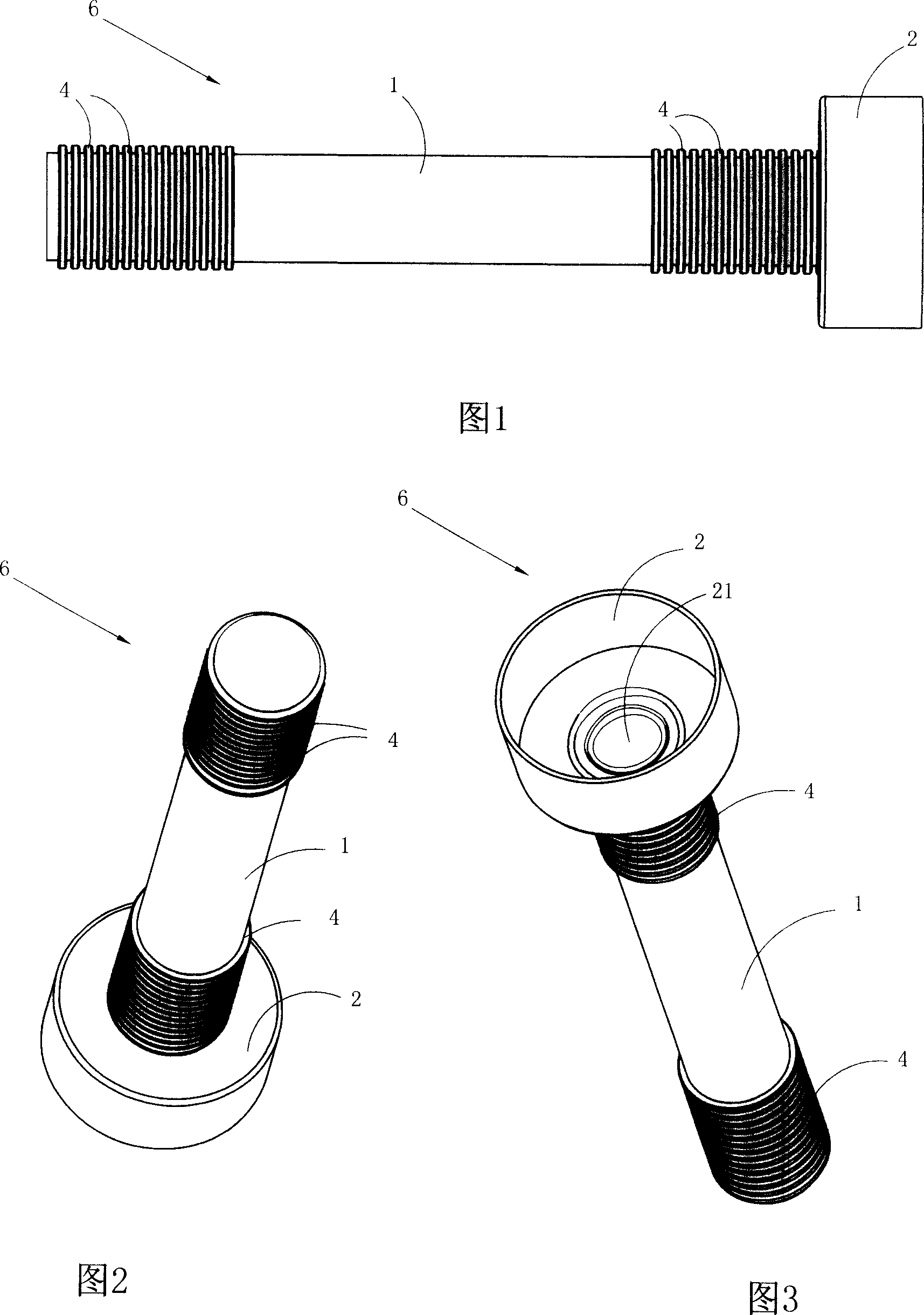
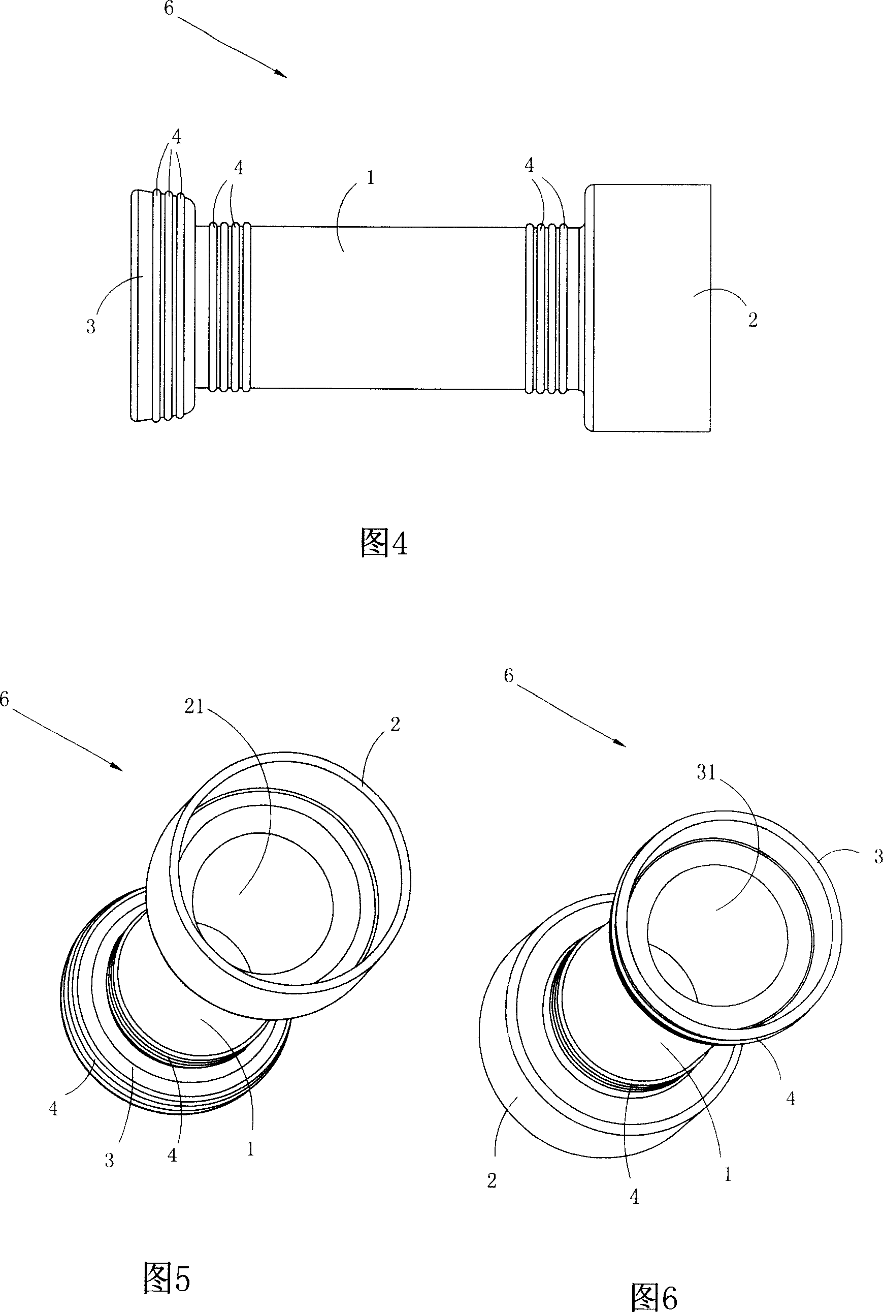
[0040] See Fig. 1 to Fig. 3, have shown the first kind of embodiment of the insulating cover 6 of the present invention, in this embodiment, described insulating cover 6 has hollow tubular insulating cover 1, and with insulating cover 1 side end Connected plug guard 2.

[0041] The basic shape of the plug protective cover 2 is a hollow cup with a round opening with a through hole 21 at the center of the end face connected to the insulating sleeve 1 at the bottom. The edges of the through holes 21 are fixedly connected to form one piece. The caliber of the plug shield 2, ie the maximum aperture of the cup-shaped body, is larger than the aperture of the insulating sleeve 1, so as to enclose the plug in the conductive rod assembly.

[0042] The outer surface of the insulating sleeve 1 is also provided with a plurality of anti-creepage rings 4, and the anti-creepage rings 4 are annular convex lines attached to the outer surface of the insulating sleeve 1. The anti-creepage rings ...


PUM


Abstract

This invention discloses one insulation protection cover and its conductive composite part, wherein, the cover has one hollow insulating cover with one side connected with plug protection cover; the conductive parts have metal conductive bar and insulation cover; the metal conductive bar comprises column conductive bar body and plug fixed on one side of body; the said insulation protection cover has hollow insulation cover set on the outer surface of conductive body; the said insulation cover one end is set with plug protection cover; the said plug is inside plug protection cover.

Description

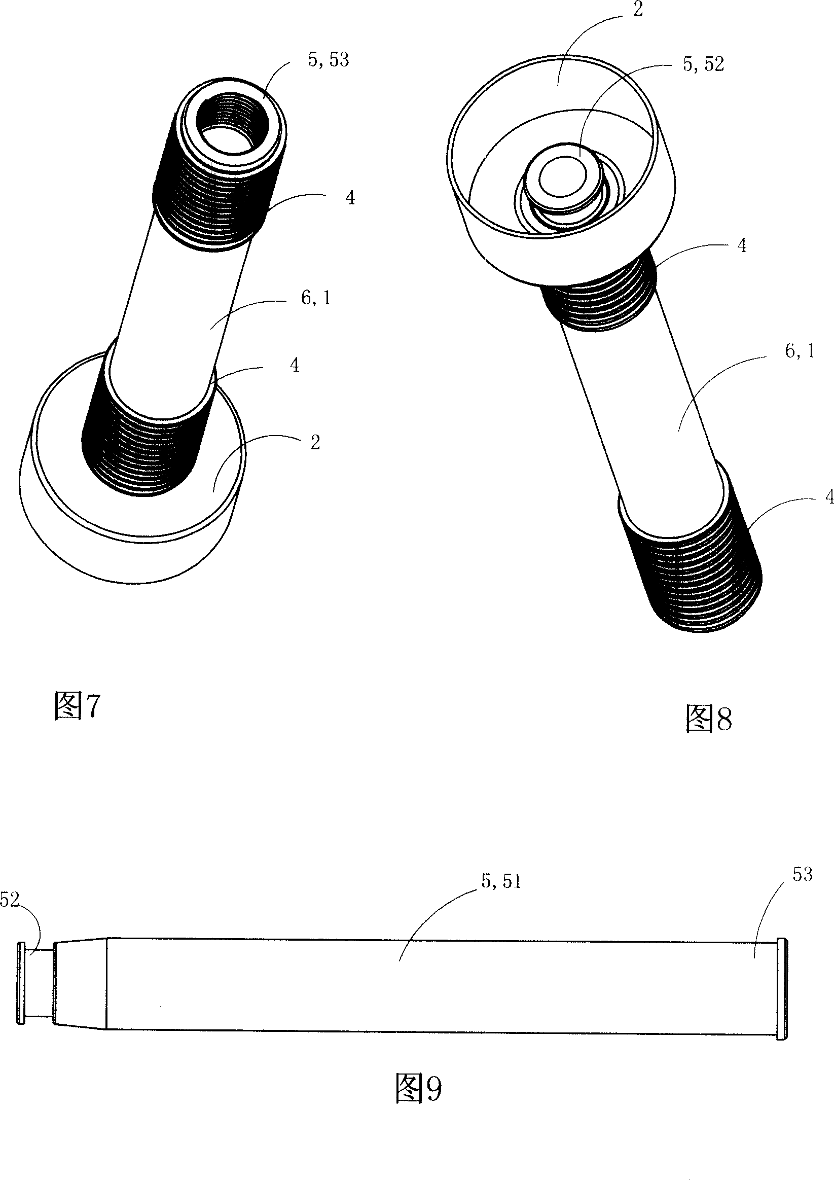
technical field [0001] The invention belongs to the technical field of electric equipment, and in particular relates to an insulating shield and a conductive rod assembly using the insulating shield. Background technique [0002] In high-voltage electrical appliances such as circuit breakers and combined electrical appliances (GIS) with voltage levels above 10KV, the conductors used to connect components and conduct current are called conductive rods. The current passing through the conductive rod is relatively large, generally 400-4000A, and is usually made of copper rod or copper tube. Commonly used conductive rods mainly include a tubular conductive rod main body (51) and a plug (52) fixed on one side of the conductive rod main body. The conductive rod main body and the plug can be formed into one piece at one time. [0003] Due to the short distance between the conductive rods and the ground, the voltage is high, and accidents are prone to creepage and ignition, so it i...

Claims


Application Information

Patent Timeline
Patent Type & Authority Applications(China)
IPC IPC(8): H01B17/58H01B7/02H01R11/11
Inventor 陈微丹
Owner ZHEJIANG DONGYA ELECTROMECHANICAL
Learn More