A passive optical network system for realization of TDM service based on Ethernet

A passive optical network and Ethernet technology, applied in the field of Ethernet-based passive optical networks, can solve the problems of resource consumption, high cost, and difficulty in implementation.

Active Publication Date: 2007-05-30
广州市高科通信技术股份有限公司
View PDF0 Cites 5 Cited by
  • Summary
  • Abstract
  • Description
  • Claims
  • Application Information

AI Technical Summary

Problems solved by technology

The implementation of this method is difficult, the cost is high, and the accuracy of the recovered clock is not satisfactory. In actual use, the provider of the IP service needs to guarantee the QoS of the TDM service data packet, which is inconvenient and consumes resources.

Method used


Image

  • A passive optical network system for realization of TDM service based on Ethernet
  • A passive optical network system for realization of TDM service based on Ethernet

Examples


Embodiment Construction

[0024] The present invention will be further described below in conjunction with the accompanying drawings.

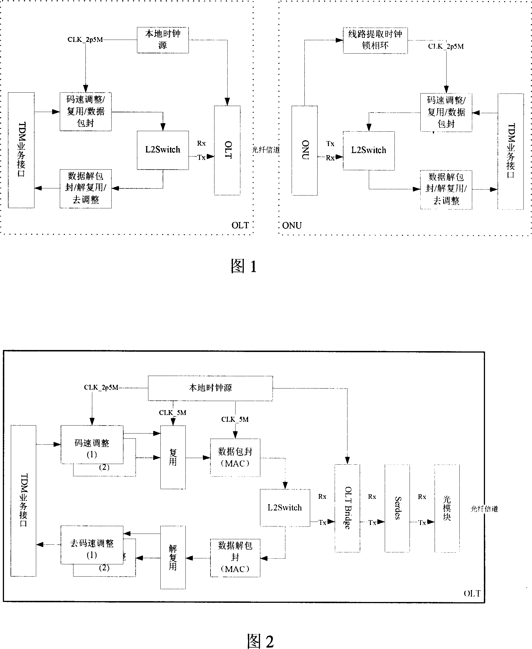
[0025] The composition block diagram of the present invention is as shown in accompanying drawing 1, and the left part in the figure is the OLT terminal equipment, and the right part is the ONU terminal equipment. The OLT-side device uses the local clock source as the sending clock of the PON port and adapts the TDM service data to the PON sending data to ensure that the adapted TDM service data flow is synchronized with the sending clock of the PON port. Data multiplexing and encapsulation of the multiplexed data are performed simultaneously during the adaptation process, and the encapsulation format is the same as that of the Ethernet data frame. For receiving the TDM data frame sent by the ONU, the local clock source is also used to extract the TDM data.

[0026] The signal flow diagram of the OLT side is shown in Figure 2. After adopting the local clock source as ...


PUM


Abstract

This invention provides one light network system without source based on Ethernet of TDM business, which comprises fiber branch connection light path terminal and light internet unit, wherein, the terminal and unit are set with TDM business adapter; the said terminal TDM business adapter adopts light network send clock to seal the TDM business data or analysis; the said light network unit TDM business adapter by use of light network receive clock for analysis or sealing.

Description

technical field [0001] The invention belongs to the Ethernet-based passive optical network technology, and in particular relates to an Ethernet-based passive optical network system for realizing TDM services. technical background [0002] The Ethernet-based passive optical network EPON system realizes low-cost, long-distance high-speed access, and is considered to be a new trend of broadband access. Since the EPON system is based on Ethernet technology and does not provide an end-to-end transparent clock, when providing TDM with strict timing requirements, the timing clock signal must be recovered by using system timing or simulation. The current common practice in the industry is to use circuit emulation, which encapsulates TDM service data and clock information into IP data packets, and recovers service data and clock signals from the IP data packets when receiving them. The implementation of this method is difficult, the cost is high, and the accuracy of the recovered cl...

Claims


Application Information

Patent Timeline
IPC IPC(8): H04B10/12H04J3/16H04L12/56H04Q11/04H04L29/06H04L47/43
Inventor 张贤德周昭荣
Owner 广州市高科通信技术股份有限公司
Why Eureka
Try Eureka