Multilayer electronic component and injection system using same

An electronic component, laminated technology, applied in the manufacture/assembly of piezoelectric/electrostrictive devices, electrical components, piezoelectric/electrostrictive/magnetostrictive devices, etc. Large, easy to short-circuit and other problems, to achieve the effect of suppressing short-circuit

Active Publication Date: 2007-05-30
KYOCERA CORP
View PDF2 Cites 9 Cited by
  • Summary
  • Abstract
  • Description
  • Claims
  • Application Information

AI Technical Summary

Problems solved by technology

In this molding method, the thickness variation of the tape may be large due to the mixing of impurities or drying unevenness, and the distance between the internal electrodes 2 may be shortened, so that an electrical short circuit between the internal electrodes 2 may easily occur.
In particular, if the thickness of the sheet is increased to improve insulation, the deviation will increase
[0019] Therefore, if a high voltage is applied at a high frequency for driving in order to achieve the above-mentioned high responsiveness and large displacement, there is a problem that a short circuit occurs between internal electrodes.
[0020] In particular, when driving under high temperature and high humidity, there is a problem that a short circuit is likely to occur between internal electrodes to which different voltages are applied due to the migration of electrode components.

Method used


Image

  • Multilayer electronic component and injection system using same
  • Multilayer electronic component and injection system using same
  • Multilayer electronic component and injection system using same

Examples


Embodiment approach 1

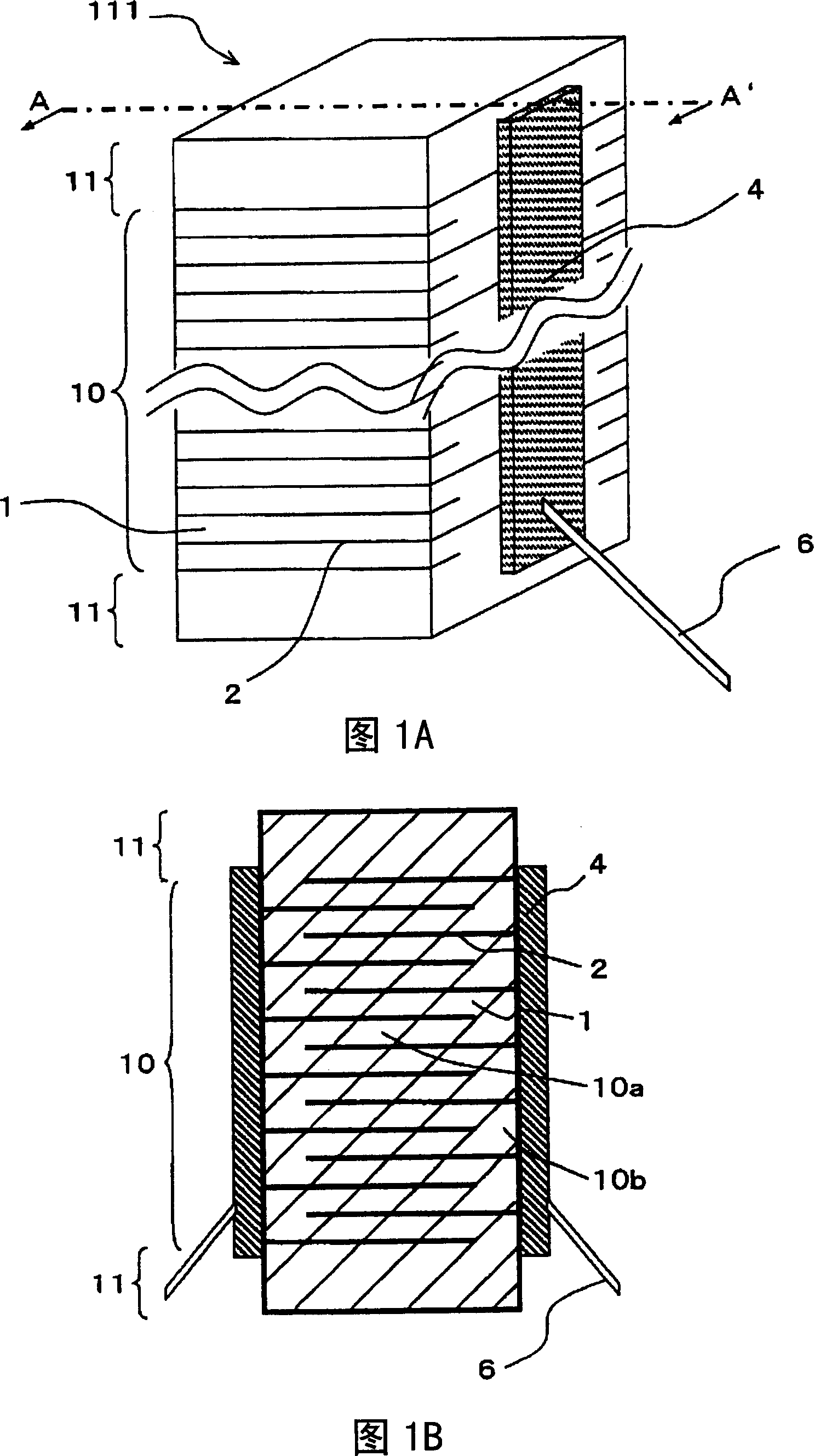
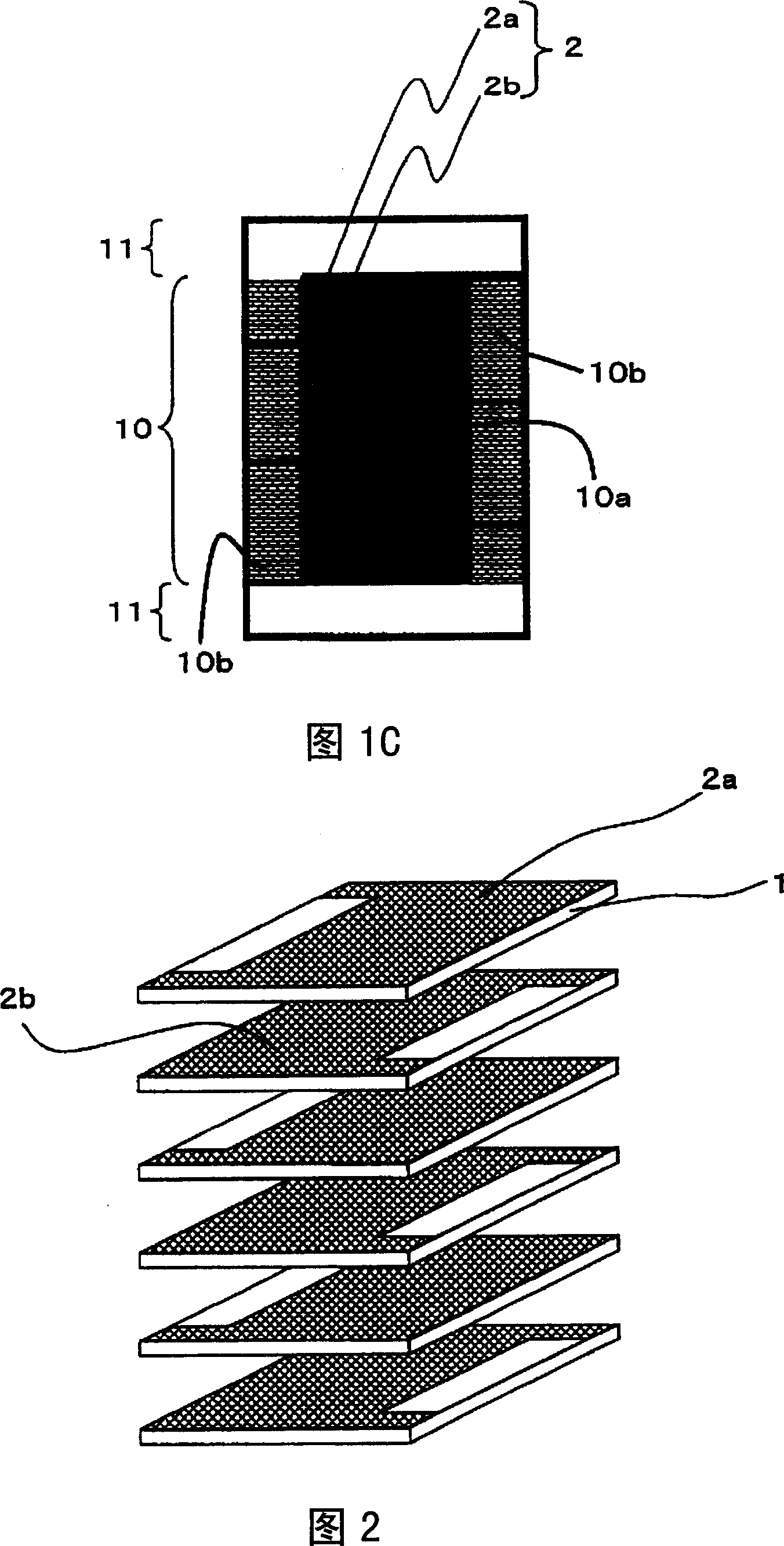
[0068] 1A, 1B, and 1C show the configuration of a multilayer piezoelectric actuator as one form of the multilayer electronic component according to Embodiment 1 of the present invention, FIG. 1A is a perspective view, and FIG. 1B is A-A of FIG. 1A ’ line, FIG. 1C is an enlarged view showing a part of FIG. 1B enlarged.

[0069] In the multilayer piezoelectric actuator according to the first embodiment, as shown in FIG. 1A , an effective layer 10 formed by alternately laminating piezoelectric bodies 1 and internal electrodes 2 , and an A pair of external electrodes 4 are provided on side surfaces of a laminate 111 composed of protective layers 11 provided at both ends. In addition, as shown in FIG. 1B and FIG. 1C, the effective layer 10 is composed of an active portion 10a (hereinafter referred to as a displacement portion 10a) and an inactive portion 10b (hereinafter referred to as a non-displaced portion 10b), wherein the active portion 10a is formed by combining with a Among...

Embodiment approach 2

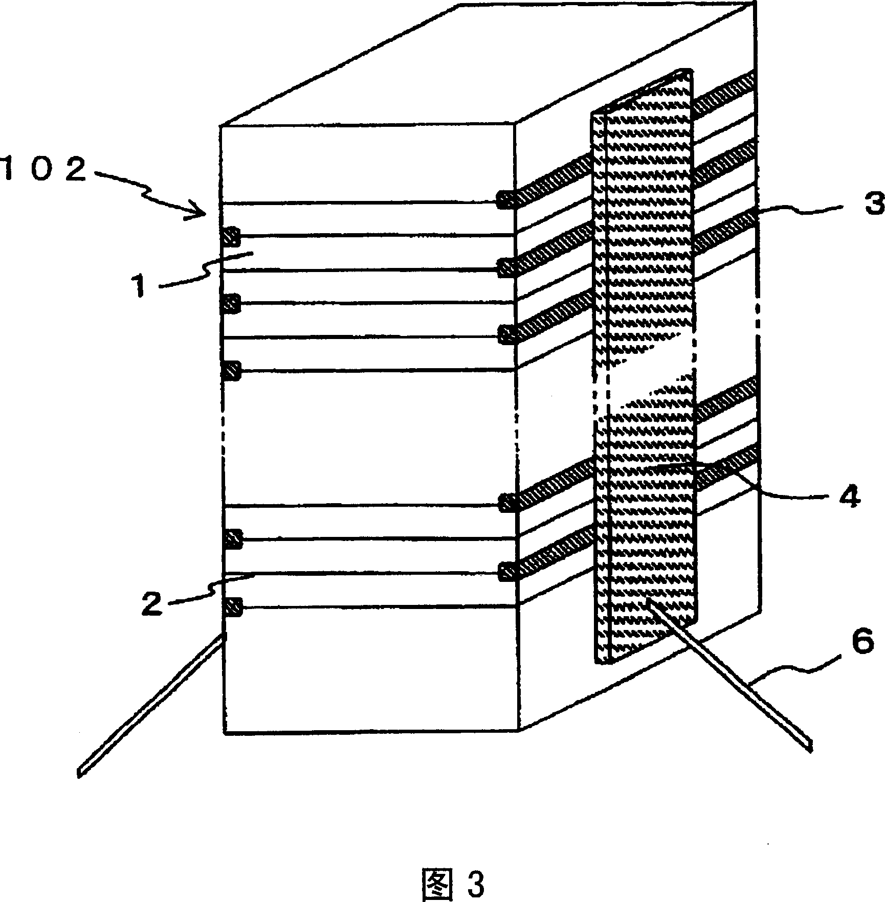
[0107] The multilayer actuator of Embodiment 2 is another example of the multilayer electronic component of the present invention.

[0108] As shown in FIG. 3 , the multilayer actuator according to the second embodiment is constituted by facing each other with square columnar laminated bodies 102 formed by alternately laminating a plurality of piezoelectric bodies 1 and a plurality of internal electrodes 2 . The two sides of the internal electrode 2 are different from each other and are covered with an insulator 3 every other layer, and the end of the internal electrode 2 not covered by the insulator 3 is connected to the external electrode 4, and each external electrode 4 is connected. Fix wire 6.

[0109] Piezoelectric bodies 1 are disposed between internal electrodes 2 , and a predetermined voltage is applied to each of piezoelectric bodies 1 via internal electrodes 2 , causing displacement in piezoelectric bodies 1 by the inverse piezoelectric effect.

[0110] Furthermore...

Embodiment approach 3

[0128] The multilayer electronic component according to Embodiment 3 of the present invention is also a multilayer piezoelectric element (multilayer piezoelectric actuator), and is configured as follows.

[0129] Here, FIG. 4A is a perspective view, and FIG. 4B is a perspective development view showing a laminated state of the piezoelectric layer and the internal electrode layer.

[0130] In the multilayer piezoelectric element according to Embodiment 3, as shown in FIGS. 4A and 4B , on a pair of opposing side surfaces of a laminated body 113 constituted by laminating piezoelectric bodies 1 and internal electrodes 2 alternately, There are external electrodes 4 , and the ends of the internal electrodes 2 exposed at every other layer on the side surfaces thereof are electrically connected to the external electrodes 4 . In addition, protective layers 11 formed of piezoelectric bodies 1 are provided on the lamination layers at both ends of the lamination direction of the laminatio...


PUM


Abstract

A multi-layer electronic component comprising: a stack having an effective region formed by stacking at least one dielectric layer and a plurality of internal electrodes consisting of first and second internal electrodes one on another and protective layers provided on both ends of the effective region in the stacking direction; and external electrodes formed on two side faces of the stack with one of which being connected to the first internal electrode and the other external electrode being connected to the second internal electrode, wherein the effective region consists of an active region where adjacent first internal electrode and second internal electrode oppose each other and an inactive region located outside of the active region in which the first internal electrodes or the second internal electrodes oppose each other, and wherein the active region and the inactive region have different colors to appreciate a border between the displacement section and no-displacement section obviously.

Description

technical field [0001] The present invention relates to multilayer electronic components, which are used, for example, in multilayer ceramic capacitors and multilayer piezoelectric elements. In particular, it relates to multilayer electronic components such as multilayer piezoelectric actuators used in piezoelectric transformers, precision positioning devices such as automotive fuel injection devices, optical devices, and vibration prevention drive elements, and the use of the Jetting device for multilayer electronic components. Background technique [0002] Conventionally, as a multilayer electronic component, for example, a multilayer piezoelectric actuator in which piezoelectric bodies and internal electrodes are alternately laminated is known. In this multi-layer piezoelectric actuator, voltage is applied to the piezoelectric body to extend it by several μm to several tens of μm, and this becomes the driving force source of the actuator. Multilayer piezoelectric actuat...

Claims


Application Information

Patent Timeline
Patent Type & Authority Applications(China)
IPC IPC(8): H01L41/083H01L41/187H01L41/22H02N2/00
Inventor 中村成信近藤光央佐藤政宏
Owner KYOCERA CORP
Why Eureka
Try Eureka