Cutting device

A cutting device and chip technology, which is used in fine working devices, maintenance and safety accessories, stone processing equipment, etc., can solve the problems of difficult to remove chips and defective products, and achieve the effect of preventing defective products and preventing adhesion.

Active Publication Date: 2007-06-06
DISCO CORP
View PDF1 Cites 7 Cited by
  • Summary
  • Abstract
  • Description
  • Claims
  • Application Information

AI Technical Summary

Problems solved by technology

As a result, there is a problem that it is more difficult to remove chips
[0010] Moreover, if the semiconductor chip divided by such a cutting device is moved directly to the subsequent process in a state where cutting chips are attached to the semiconductor chip, the cutting chips will fall on the circuit of the product and become a cause of product failure.

Method used


Image

  • Cutting device
  • Cutting device
  • Cutting device

Examples


Embodiment Construction

[0046] Preferred embodiments of the present invention will be described in detail below with reference to the accompanying drawings.

[0047] In addition, in this specification and drawing, the structural element which has substantially the same function structure is denoted by the same code|symbol, and the repeated description is abbreviate|omitted.

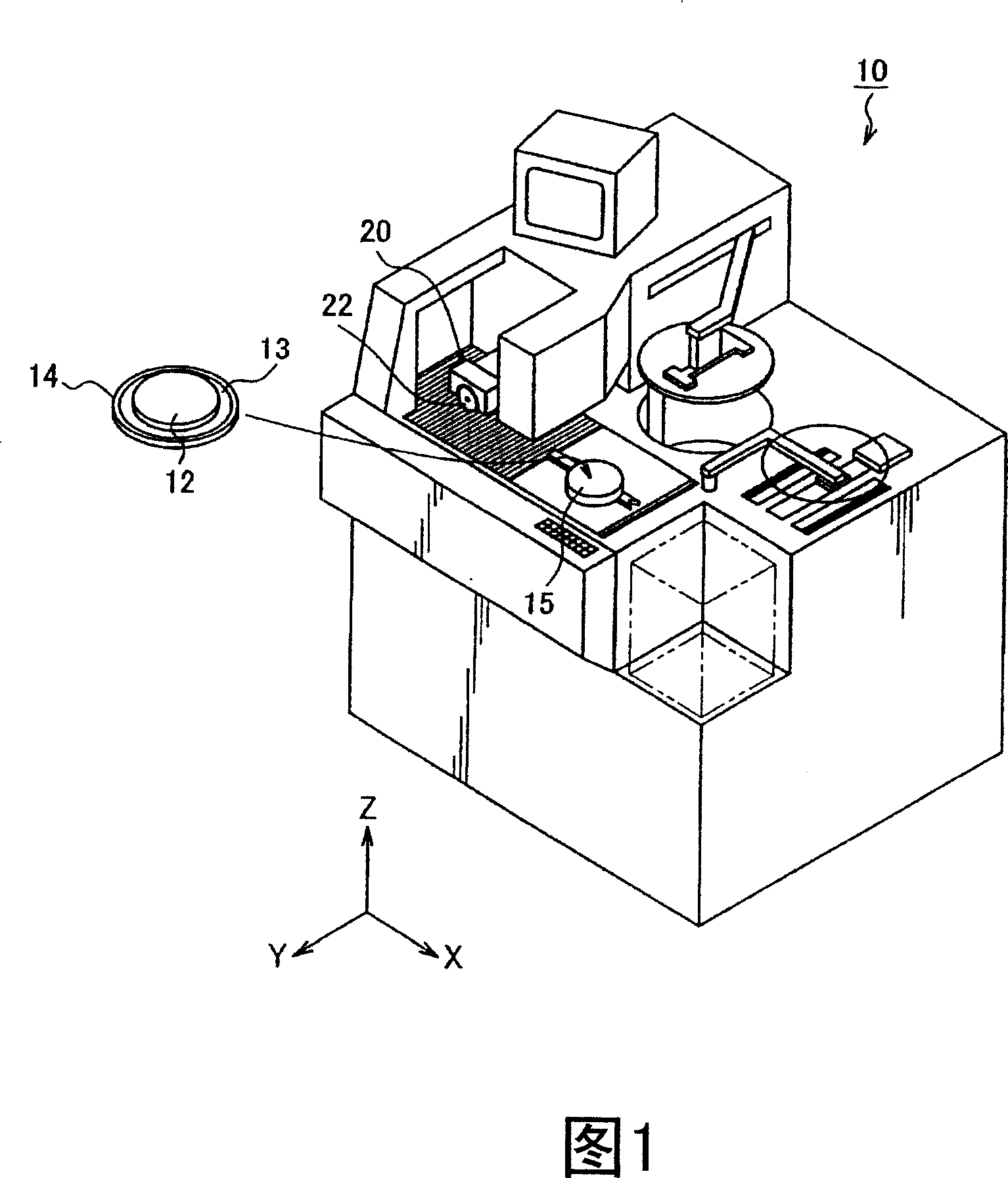
[0048] First, the overall configuration of a cutting device 10 as an example of a cutting device according to an embodiment of the present invention will be described based on FIG. 1 . In addition, FIG. 1 is a perspective view showing the overall configuration of a cutting device 10 according to the present embodiment.

[0049] As shown in FIG. 1 , the cutting device 10 is mainly provided with, for example, a chuck table 15 as an example of a holding mechanism for holding the workpiece 12, a cutting unit 20 as a cutting device for cutting the workpiece 12, and a cutting unit moving mechanism (not shown) and chuck table moving m...


PUM


Abstract

The invention provides a cutting device which more surely prevents adhering of chips to the surface of a workpiece. This cutting device is provided with: a cutting blade, a cutting liquid supply means for supplying cutting liquid to the cutting blade and a machining point of the workpiece; and a blade cover arranged to cover an outer periphery of the cutting blade. The cutting device is further provided with a cutting chip control means oppositely arranged to hold the cutting blade on both spindle axial direction sides of the cutting blade to inject liquid toward a position separated by a prescribed distance from the machining point on the surface of the workpiece from both sides of the cutting blade. The cutting chip control means forms liquid walls along the cutting direction on both the sides of the cutting blade not to splash the chips generated by cutting the workpiece in the spindle axial direction by injecting the liquid, and separates the chips from the surface of the workpiece by a flow of the injected liquid.

Description

technical field [0001] The present invention relates to a cutting device, in particular to a cutting device capable of preventing cutting chips from adhering to the surface of a workpiece. Background technique [0002] For example, in the manufacturing process of semiconductor equipment, circuits such as ICs and LSIs are formed in a plurality of regions divided by grid-like blocks (cutting lines) formed on the surface of a roughly disc-shaped semiconductor wafer or other workpiece, and circuits such as ICs and LSIs are formed along the Semiconductor chips are fabricated as the blocks are divided to form the various regions of the circuit. The semiconductor chips thus manufactured are packaged and widely used in electrical equipment such as cellular phones and personal computers. [0003] As a dividing device for dividing such a workpiece such as a semiconductor wafer, a cutting device is generally used as a dicing device. This cutting device performs cutting by relatively ...

Claims


Application Information

Patent Timeline
Patent Type & Authority Applications(China)
IPC IPC(8): B28D5/02H01L21/78H01L21/301B23Q11/02
Inventor 佐藤正视
Owner DISCO CORP
Why Eureka
Try Eureka