Hydraulic directio machine

A steering machine and hydraulic technology, applied in the direction of hydraulic steering gear, etc., can solve the problems that the steering machine is difficult to achieve ergonomics, the angle of the steering wheel cannot be adjusted, and the steering force is increased, so as to simplify the design idea, the steering is easy and flexible, and the steering is reduced. The effect of resistance

Inactive Publication Date: 2007-06-06
陆松
View PDF0 Cites 3 Cited by
  • Summary
  • Abstract
  • Description
  • Claims
  • Application Information

AI Technical Summary

Problems solved by technology

In addition, the steering machine is rigidly fixed on the chassis or body of the walking machine through the steering frame, the angle of the steering wheel cannot be adjusted, and the comfort is poor.
With the increase in the size and load of the transport vehicle, the worm gear steering gear and the recirculating ball steering gear came in

Method used


Image

  • Hydraulic directio machine
  • Hydraulic directio machine

Examples


Example Embodiment

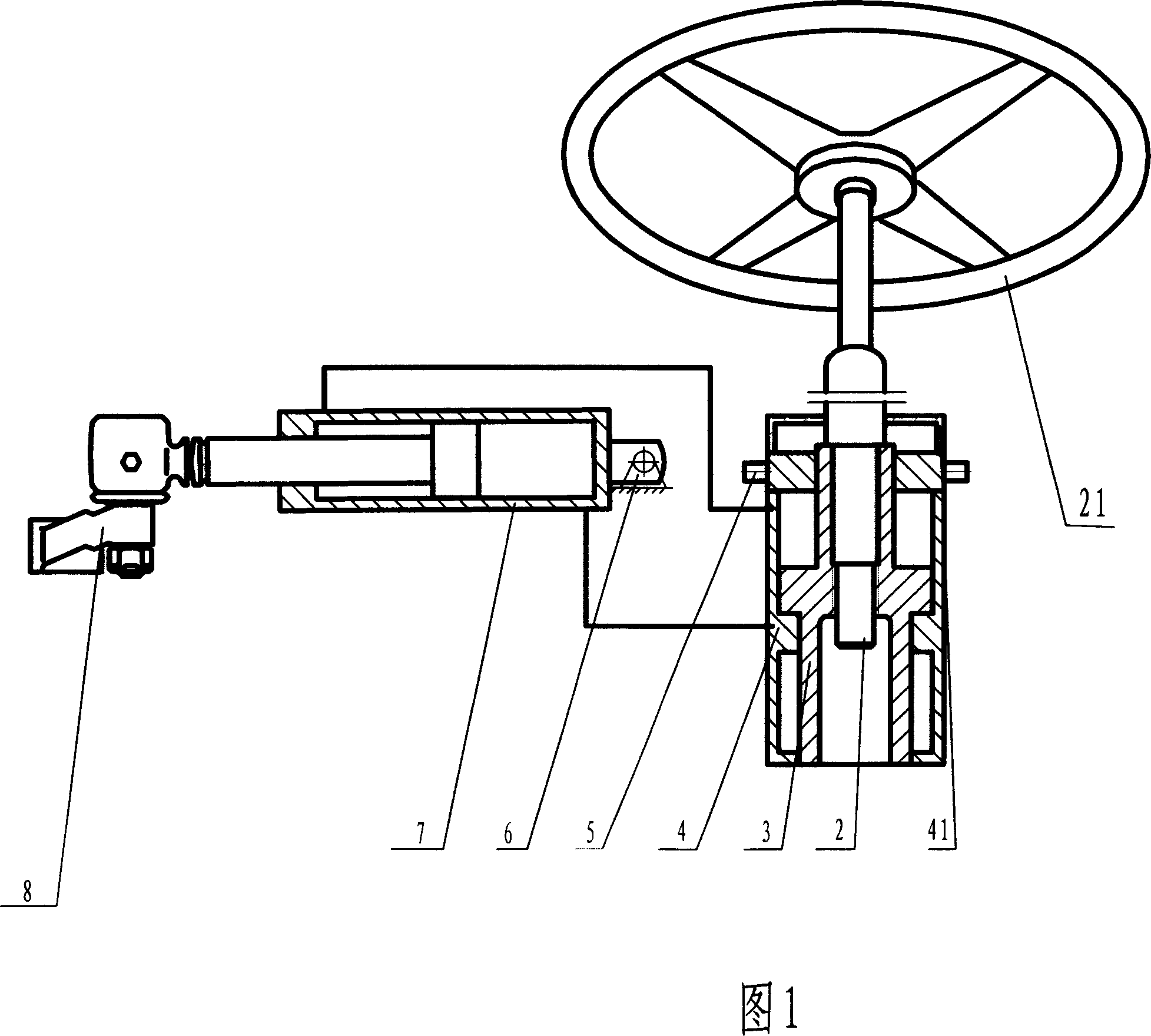
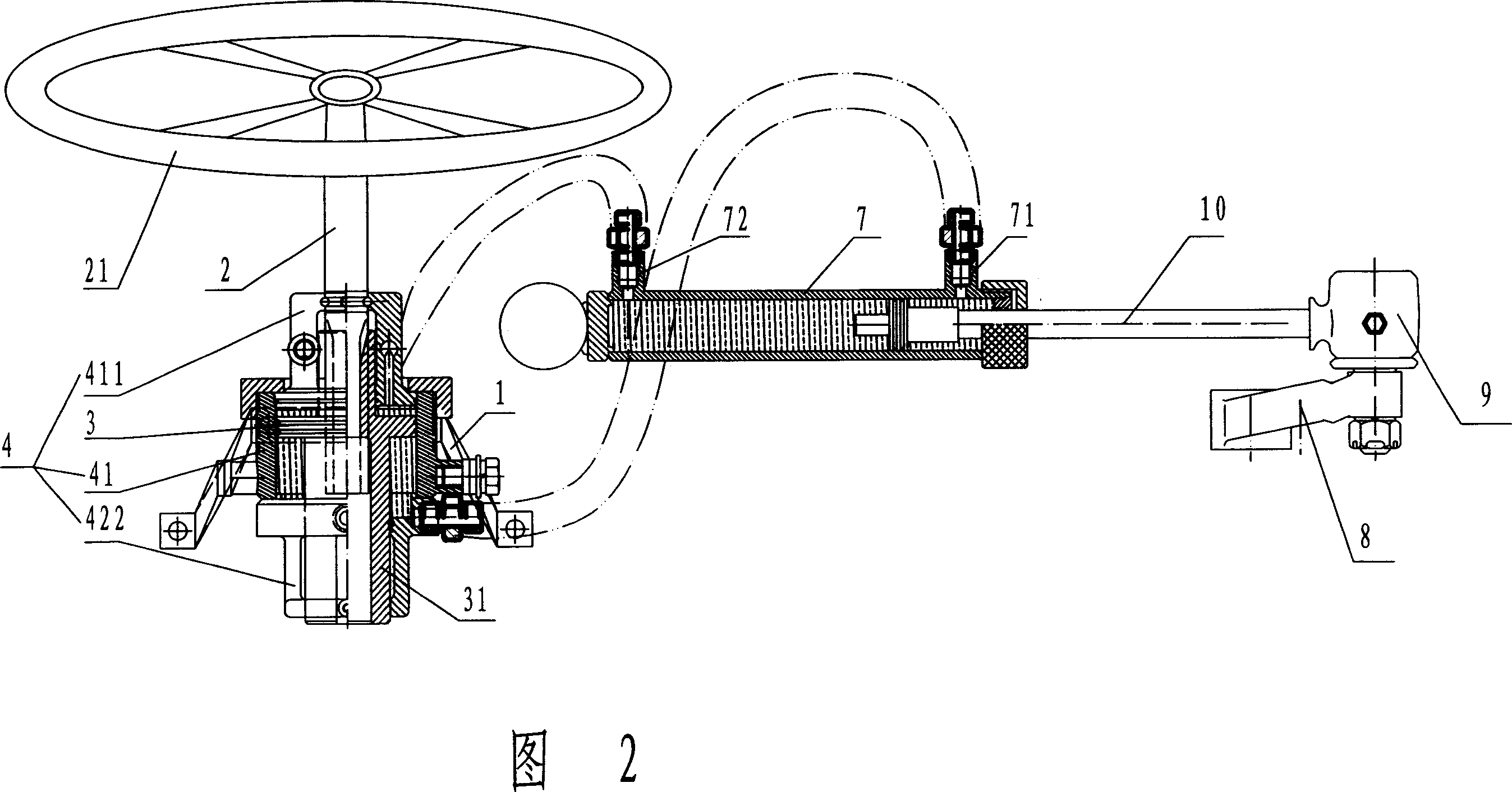
[0013] As shown in the drawings, the hydraulic steering machine according to the present invention includes a steering shaft 2 and a steering wheel fixedly mounted on the top of the steering shaft 2. The lower end of the steering shaft 2 is inserted into the driving cylinder 4. The driving cylinder 4 is fixedly installed on the bracket 1 and fixed on the frame or chassis through the bracket 1. According to the installation position and space of different vehicle types, the bracket 1 can adopt various structural forms.

[0014] The driving cylinder 4 includes a cylindrical cylinder 41 with upper and lower end covers, and a driving cylinder piston 3 installed in the cylinder 41. The upper end cover 411 is fixedly installed on the upper end of the cylinder body 41 by the upper cover nut, and the lower end cover 422 is fixedly installed on the lower end of the cylinder body 41; A card slot, the annular card slot is clamped in the shaft hole of the upper end cover.

[0015] The functio...


PUM


Abstract

The present invention relates to steering operation mechanical for motor tricycle, three wheeler, low speed transport vehicle, etc and is especially one kind of hydraulic direction machine. The hydraulic direction machine includes one shaft with annular slot, one steering wheel in the top of the shaft, one driving oil cylinder the shaft is inserted in, one executing oil cylinder with oil returning port and oil inlet communicated separately with the oil inlet and the oil returning port of the driving oil cylinder, and one rocker connected through a round head to the top of the piston in the executing oil cylinder. The hydraulic direction machine has driving mechanism and executing mechanism separately set and connected through middle hose, and this result in convenient design and installation of the steering mechanism and high adaptability.

Description

technical field [0001] The invention relates to a steering operation mechanism for three-wheeled motorcycles, three-wheeled automobiles, low-speed transport vehicles, tractors and wheeled self-propelled machines, in particular to a hydraulic steering machine. Background technique [0002] For a long time, agricultural machinery tractors, three-wheel vehicles, four-wheel low-speed vehicles, rice transplanters, etc. all use the steering wheel to drive the gear (or worm) on the steering shaft through the spline to rotate, and the gear drives the rack (or turbine and crank arm) The rotary motion is changed into linear motion, the rack (knuckle arm) is connected with the rocker arm on the main shaft of the front fork through the pin shaft (tie rod), the reciprocating linear motion is changed into swing motion, and the power is transmitted between the parts through rigid connections. The collision and friction between the components are transmitted to the steering wheel through th...

Claims


Application Information

Patent Timeline
IPC IPC(8): B62D3/14
Inventor 陆松
Owner 陆松
Why Eureka
Try Eureka