Knitting machine with air jet

An air conveying device and knitting machine technology, which is applied in the field of knitting machines and can solve problems such as inability to achieve cleaning effects

Inactive Publication Date: 2007-06-06
GROZ BECKERT KG
View PDF1 Cites 1 Cited by
  • Summary
  • Abstract
  • Description
  • Claims
  • Application Information

AI Technical Summary

Problems solved by technology

In this way, a broad cleaning effect cannot be achieved

Method used


Image

  • Knitting machine with air jet
  • Knitting machine with air jet
  • Knitting machine with air jet

Examples


Embodiment Construction

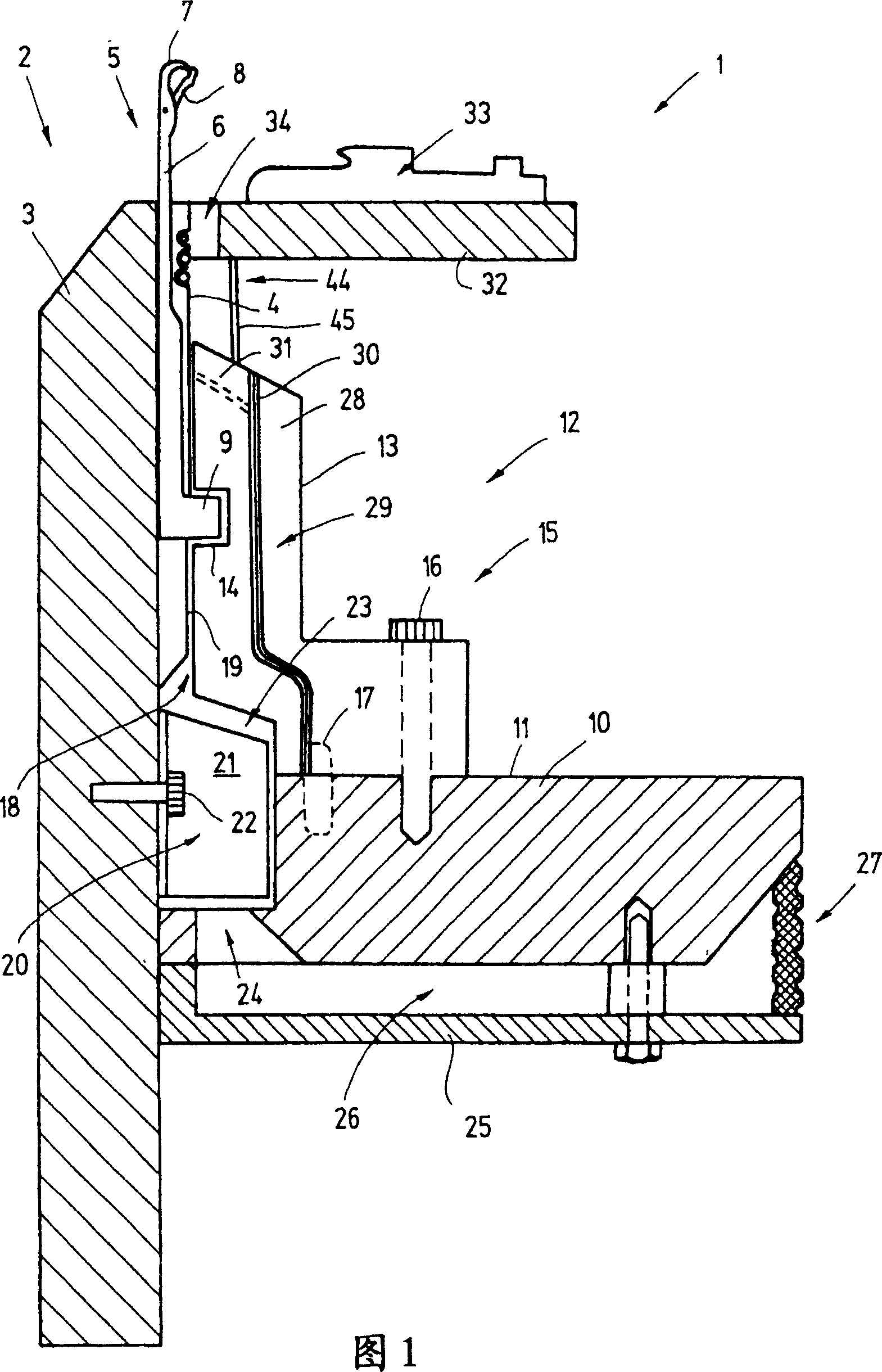
[0025] FIG. 1 shows a knitting machine 1, which is, for example, a circular knitting machine. Its needle bed 2 has the shape of a needle cylinder 3 provided on its outside with vertical needle tracks / slots 4 extending parallel to its axis of rotation. Arranged in the needle tracks 4 are knitting tools 5 , for example in the form of latch needles 6 shown, which are movable along the respective track. On the end side, the latch needle 6 has a hook 7 protruding from the needle track 4 and associated with a pivotably mounted tongue 8 . The body of the latch needle 6 extends into the needle path 4 and is provided with a heel 9 for driving the latch needle.

[0026] While the cylinder 3 is working in rotation, an annular triangular support plate 10 surrounding it on the outside remains stationary. On its substantially planar upper side 11 , the triangular support plate 10 has a knitted triangular seat 12 (Strickschlossmantel), which consists of a plurality of cams or cam segments ...


PUM


Abstract

The knitting machine ( 1 ) according to the invention is provided with an air-conducting device ( 21 ) for conducting air into an air guidance space ( 18 ) that is embodied between the cam assembly ( 12 ) and the knitting cylinder ( 3 ). As a result of this air guidance space, cleaning air is supplied directly to the knitting tools ( 5 ), without requiring an outer casing around the cam assembly. In the same way, the air can also be guided between a dial and its associated cam assembly to corresponding dial needles or sinkers.

Description

technical field [0001] The invention relates to a knitting machine whose knitting tools are fed with air. Background technique [0002] Knitting machines generally have a large number of knitting tools which are reciprocated by suitable drives in order to form knitted items from the supplied yarn. Dust and yarn ends, so-called lint, can collect on the knitting tools, which hinders the knitting process. [0003] From US-PS 5737942 a circular knitting machine is known with a cylinder having a plurality of needle tracks on its outside. Latch needles which are movable in the longitudinal direction and are each provided with a heel are placed in the needle track. The heels of the latch needles protrude from the needle track and are connected to a knitting cam which is formed by a plurality of knitting cams. When the needle cylinder rotates, the heels of the needles follow the contour curve of the individual knitting cams, so that the hooks of the needles move up and down accor...

Claims


Application Information

Patent Timeline
Patent Type & Authority Applications(China)
IPC IPC(8): D04B9/00D04B35/32D04B35/28
CPCD04B35/32D04B35/00
Inventor U·斯廷格尔
Owner GROZ BECKERT KG
Why Eureka
Try Eureka