
Method and system for realizing roaming

A switch and telephone number technology, applied in network data management, electrical components, network topology, etc., can solve the problems of user data dispersion, increased bandwidth, unfavorable centralized management, etc., and achieve the effect of flexible networking

Inactive Publication Date: 2007-06-06
HUAWEI TECH CO LTD
View PDF1 Cites 6 Cited by
  • Summary
  • Abstract
  • Description
  • Claims
  • Application Information

AI Technical Summary

Problems solved by technology

[0007] However, this method depends on the degree of A3 / A7 interconnection between CDMABSCs and bandwidth limitations, that is, users cannot roam between BSCs without A3 / A7 interconnection, and when the A3 / A7 interface between two BSCs The small bandwidth cannot support a large number of users to use the roaming service, and the continuous increase of A3 / A7 interconnection and increased bandwidth has caused the complexity of the roaming networking solution; in addition, each RAC in the network needs to configure user data. As far as the whole system is concerned, user data is scattered, which is not conducive to centralized management

Method used


Image

  • Method and system for realizing roaming
  • Method and system for realizing roaming
  • Method and system for realizing roaming

Examples


Embodiment Construction

[0027] In order to make the object, technical solution and advantages of the present invention clearer, the present invention will be further described in detail below with reference to the accompanying drawings and examples.

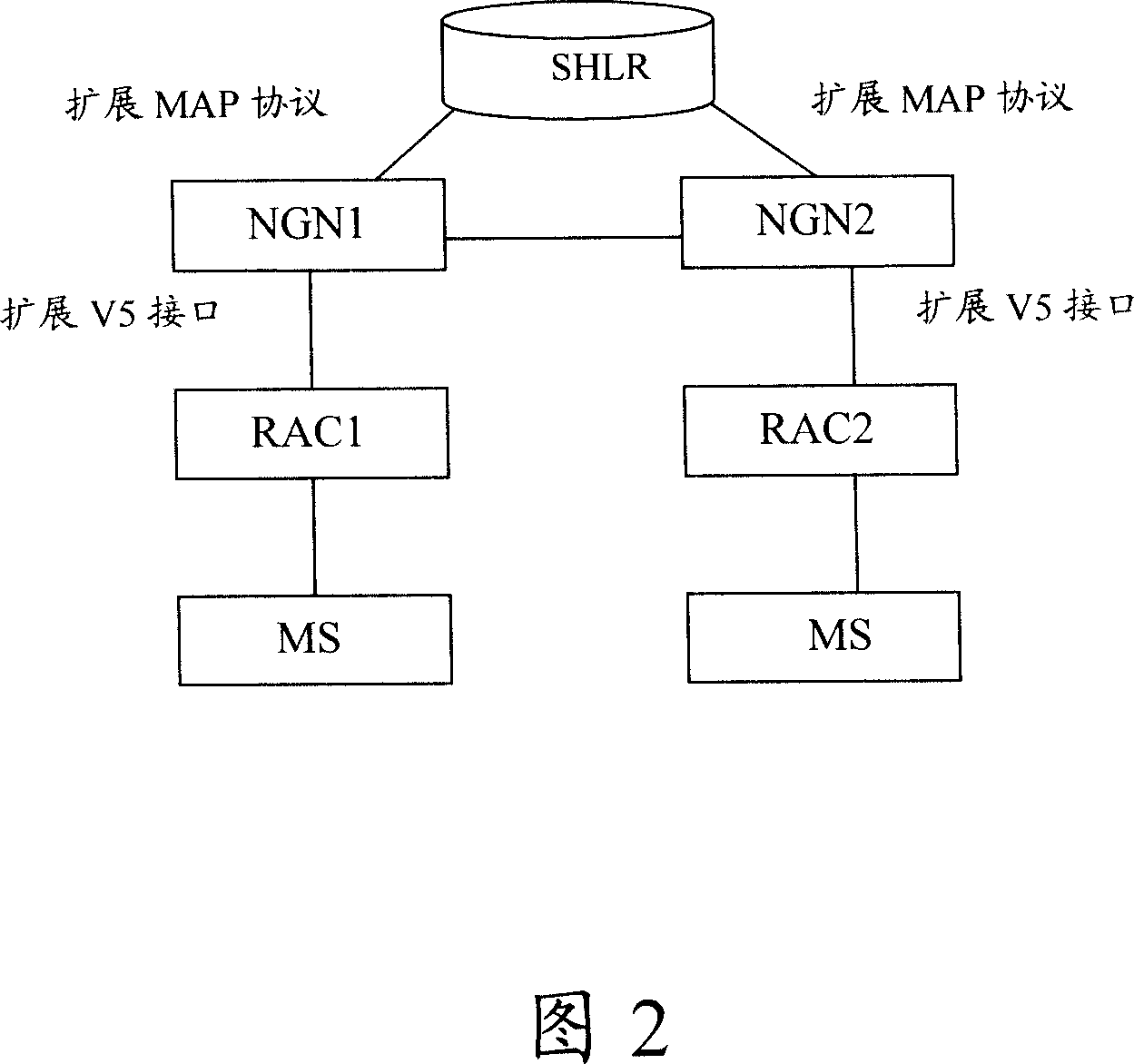
[0028] Fig. 2 is a schematic diagram of the composition and structure of the system of the present invention. As shown in Fig. 2, the system mainly includes SHLR, NGN switch and RAC.

[0029] Among them, the RAC is used to receive the location registration request from the MS, and send the MS request location registration message to the NGN switch;

[0030] The NGN switch is used to receive the MS request location registration message from the RAC, assign a roaming phone number to the MS, and send the assigned roaming phone number to the Smart Home Location Register (SHLR); after receiving the response message returned by the SHLR, the NGN The switch sends the assigned roaming phone number to the RAC;

[0031] SHLR is used to store the MS account openi...


PUM


Abstract

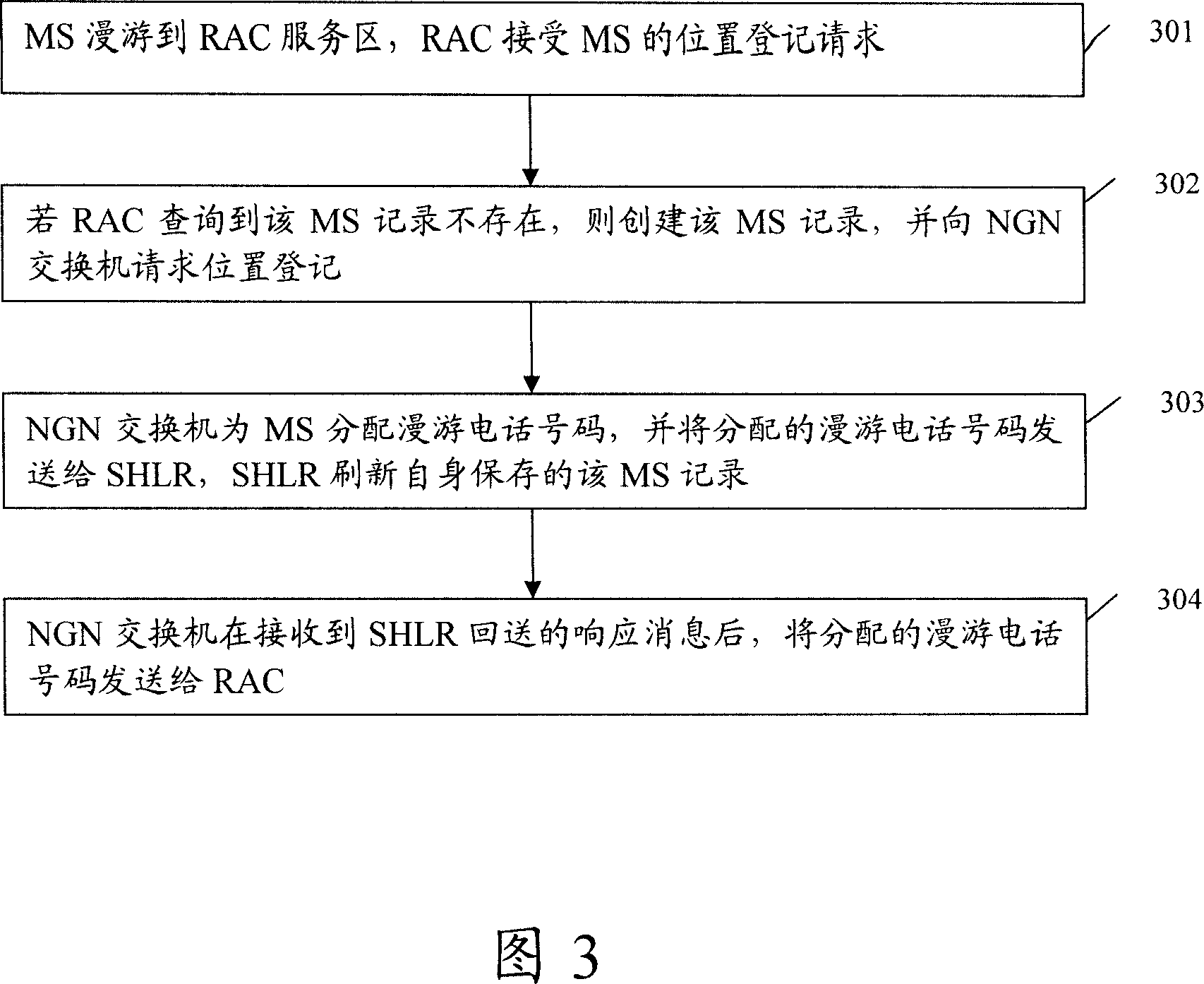
A method for realizing the roaming includes receiving position registration of MS roamed to itself service region by RAC, recording MS information if MS record is not existed and requesting position registration from NGN exchange, distributing a roaming telephone number to MS by NGN exchange and sending said number to SHLR, updating MS record stored by SHLR and sending distributed telephone number to RAC by NGN exchange after response message sent back from SHLR is received. The system for realizing said method is also disclosed.

Description

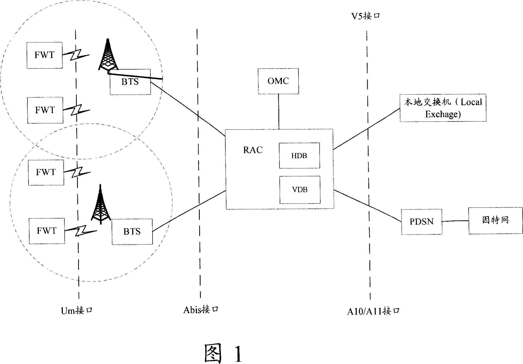
technical field [0001] The present invention relates to a wireless local loop network (WLL, Wireless Local Loop) technology, in particular to a method and a system for a user to realize roaming in a wireless local loop network. Background technique [0002] WLL network uses existing wireless technology to provide terminal business services for fixed terminal equipment or regional mobile terminal equipment. The network configuration is simple and so on. The WLL network can be used as a supplement to the wired network, providing more abundant and economical network construction solutions for fixed network operators. [0003] Figure 1 is a schematic diagram of the network structure of a WLL system based on Code Division Multiple Access (CDMA) 2000. As shown in Figure 1, the Radio Access Controller (RAC) is downwardly connected to multiple base transceiver stations (BTS) through the Abis interface. Control the access of the entire wireless channel; connect to the local exchang...

Claims


Application Information

Patent Timeline
Patent Type & Authority Applications(China)
IPC IPC(8): H04Q7/38H04Q7/24H04W8/04H04W8/06H04W8/08H04W60/04H04W84/14
CPCH04W84/14H04W60/04H04W8/06
Inventor 杨胜强
Owner HUAWEI TECH CO LTD
Learn More