Method and arrangement for inking up an applicator element of an electrophotographic printer or copier

A component and coating technology, applied in the equipment of the electric recording process applying the charge pattern, the electric recording process applying the charge pattern, the electric recording technique, etc., can solve the problem that the lines no longer have straight edges and cannot maintain an accurate screen. surface, forming too large and other problems, to achieve the effect of high printing quality

Inactive Publication Date: 2007-06-06
OCE PRINTING SYST
View PDF5 Cites 1 Cited by
  • Summary
  • Abstract
  • Description
  • Claims
  • Application Information

AI Technical Summary

Problems solved by technology

This adversely affects, for example, the reliable and neat reproduction of the individual points of the reproduction of precise lines, the generation of smooth edges and the maintenance of precise screens, as well as the homogeneous overall coloring, for example when increasing the coloring.
In this way, although a homogeneous dyeing of the surface to be dyed can be achieved by so-called dense dyeing with a large layer thickness of the toner particles, excessive dots are formed and a precise screen cannot be maintained, so that especially the lines are no longer with precise straight edges

Method used


Image

  • Method and arrangement for inking up an applicator element of an electrophotographic printer or copier
  • Method and arrangement for inking up an applicator element of an electrophotographic printer or copier

Examples


Embodiment Construction

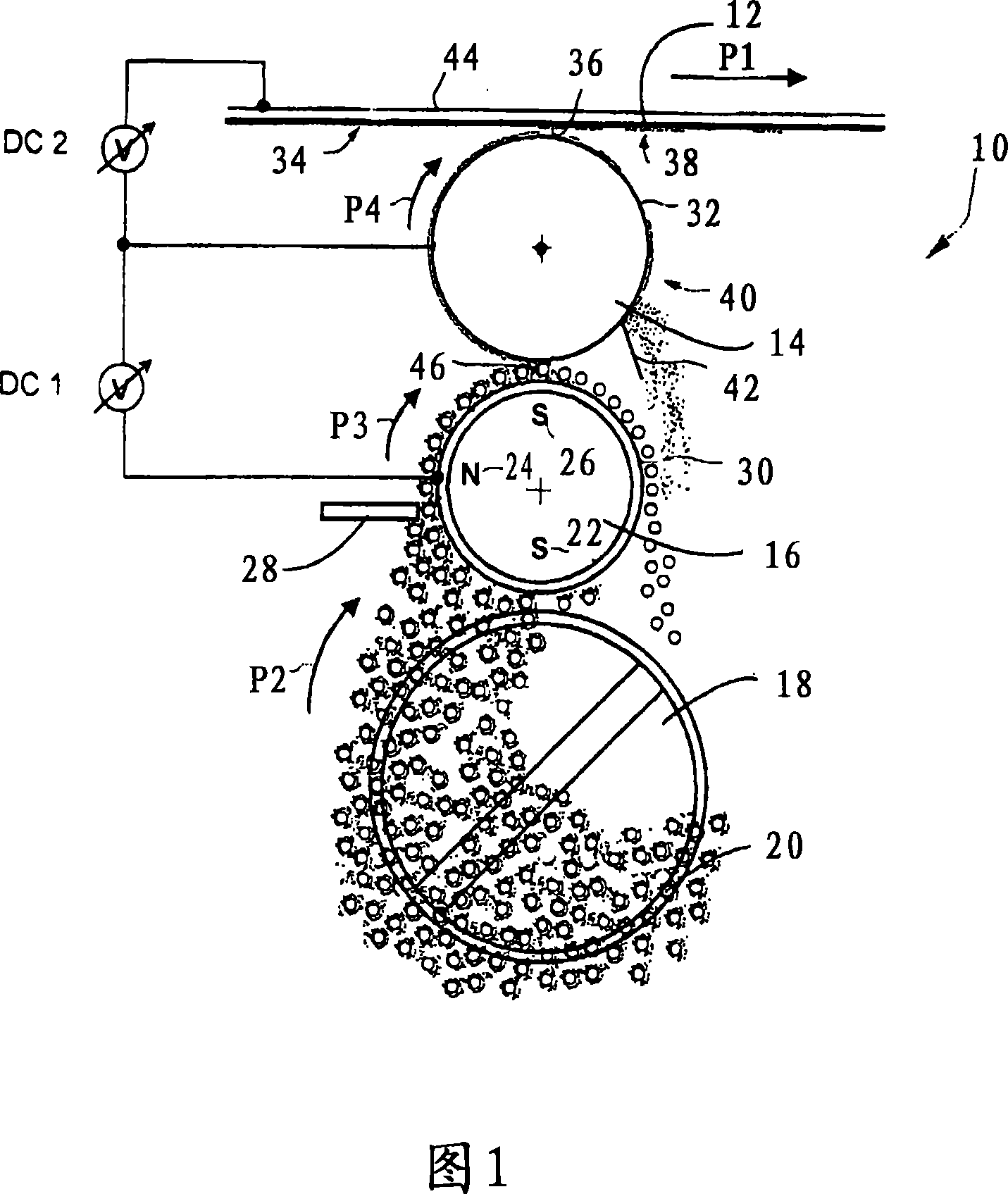
[0034] FIG. 1 shows a developer unit 10 for developing a charge pattern contained on a strip-like photoconductor 12 . The strip-shaped photoconductor 12 is driven in the direction of the arrow P1 at substantially the same speed. The developer unit 10 includes a coating roller 14 , a magnetic roller 16 and a mixing wheel 18 . The lower part of the mixing wheel 18 is located in a so-called mixture sump of the developer unit 10, in which a two-component mixture comprising toner particles and carrier particles is contained. The toner particles are charged and adhere to ferromagnetic carrier particles. The carrier particles basically serve to transport the toner particles by means of the magnetic roller 16 .

[0035] Three magnetic elements 22 , 24 , 26 are fixedly arranged inside the magnetic cylinder 16 . The magnetic elements are permanent magnets, in particular natural magnets, which extend inside the drum 16 along the full length of the drum. The longitudinal axes of the p...


PUM


Abstract

The invention relates to a method and arrangement for inking up an applicator element (14) of an electrophotographic printer or copier. A two-component mixture, which is comprised of electrically charged toner particles and of ferromagnetic particles and which adheres to the outer surface of a roller (16), is moved past a surface of an applicator element (14) to be inked up. When the two-component mixture is moved past, at least a portion of the toner particles contained in the two-component mixture is transferred to the surface of the applicator element (14) to be inked up. An electrical field is generated that acts at least upon the portion of the two-component mixture located between the surface of the roller (16) and the surface of the applicator element (14) to be inked up. The strength of the electrical field can be controlled with the aid of a control unit so that the transferred toner particles produce a preset layer thickness on the surface to be inked up.

Description

technical field [0001] The present invention relates to a method and apparatus for dyeing a coated element of an electrophotographic printing or copier, wherein the toner particles to be adhered to the outer surface of a cylinder and a ferromagnetic carrier The two-component mixture of particles moves across the surface to be dyed of an application element. At least a portion of the toner particles contained in the two-component mixture is transferred onto the surface of the application element to be colored when the two-component mixture is moved over. The invention also relates to a printing or copier for producing color images on a carrier material. Background technique [0002] Developer stations in printing and copying systems use image development methods for developing the charge pattern generated on a photoconductor, ie for developing the hidden printed image, in which the charge pattern is dyed with toner across a gap. Such a method is known, for example, from US ...

Claims


Application Information

Patent Timeline
Patent Type & Authority Applications(China)
IPC IPC(8): G03G15/09
CPCG03G15/0907
Inventor M·施洛伊泽纳U·赫利希
Owner OCE PRINTING SYST
Why Eureka
Try Eureka