Piezoelectric ultrasound motor

A piezoelectric ultrasonic and motor technology, which is applied in circuits, piezoelectric devices/electrostrictive devices, electrical components, etc., and can solve the problems of increased drive system size and complex manipulation.

Active Publication Date: 2007-06-06
PHYSIK INSTR PI
View PDF3 Cites 6 Cited by
  • Summary
  • Abstract
  • Description
  • Claims
  • Application Information

AI Technical Summary

Problems solved by technology

This structure leads to an increase in the size of the drive system in w

Method used


Image

  • Piezoelectric ultrasound motor
  • Piezoelectric ultrasound motor
  • Piezoelectric ultrasound motor

Examples


Embodiment Construction

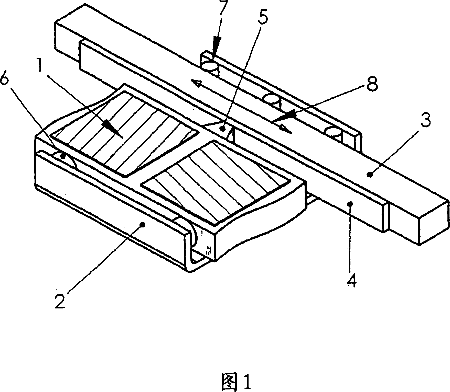
[0024] The piezoelectric ultrasonic motor of the present invention includes a piezoelectric oscillator 1 provided in a housing 2, and an element 3 (refer to FIG. 1 ) to be moved with a friction belt 4 attached thereto. Piezoelectric oscillator 1 with friction element 5 is elastically excited relative to friction band 4 by means of pressure element 4 . The element to be moved 3 is fastened to a bearing seat 7 in the motor housing 2 so that it can move in the direction indicated by the arrow 8 .

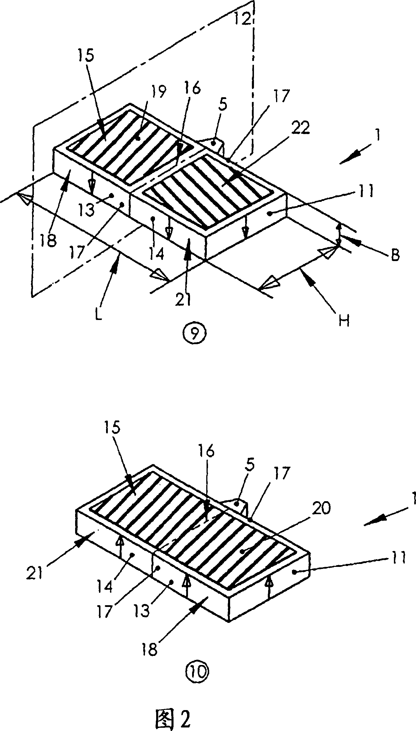
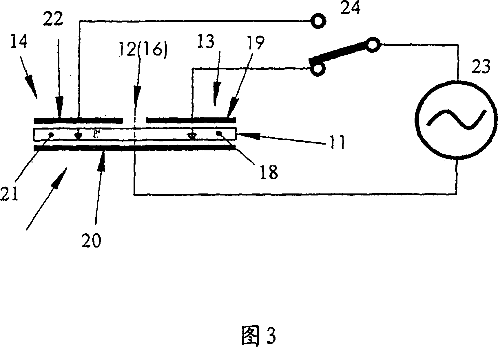
[0025] In FIG. 2, items 9, 10 are plan and bottom views of oscillator 1, respectively. The oscillator 1 is configured as a piezoelectric plate 11 of length L, height H, and width B, and is divided into two equal parts 13 , 14 by a dividing plane 12 .

[0026] The dividing plane 12 passes through the center of the oscillator length L and is perpendicular to the large side 15 of the oscillator. The trace 16 of the dividing plane 12 is indicated by the dashed line on the oscillator 1 . ...


PUM


Abstract

The invention relates to a piezoelectric ultrasound motor comprising an oscillator in the form of a piezoelectric plate having a length L and a height H, and one or two friction elements which are arranged on the oscillator and elastically pressed against the friction surface of the part to be displaced. According to the invention, the piezoelectric plate is divided into two identical parts by a cutting plane extending perpendicularly to the large surfaces, at least one of said parts containing an asymmetrical generator which generates an asymmetrical two-dimensional standing wave during the control thereof, in such a way that the friction elements arranged in the centre of the long front side of the plate perform a movement which is inclined in relation to the front side, enabling the kinetic energy to be transferred to the part to be displaced.

Description

technical field [0001] The present invention relates to linear rotary piezoelectric ultrasonic motors. The invention can be used as an electric motor in general positioning systems and fine positioning systems of plant technology. Background technique [0002] Piezoelectric ultrasonic motors with metal resonators are known from US patent US-PS 5672930, in which piezoelectric elements are adhered to the metal resonators. It has been found to be disadvantageous that due to the different thermal expansion coefficients of the metallic resonator and the piezoelectric element, it is not possible to achieve high mechanical power with these motors. Also, the metal resonator is a passive body. To achieve high-speed motion, piezoelectric elements need to be excited by means of relatively high voltages. These disadvantages reduce the reliability of motor operation and thus limit the field of application of such motors. [0003] In addition to the above-mentioned piezoelectric motor...

Claims


Application Information

Patent Timeline
IPC IPC(8): H01L41/09
CPCH02N2/026H01L41/0986H02N2/002H10N30/206
Inventor 沃拉迪米尔·韦什纽斯基阿里克斯·韦什纽斯基
Owner PHYSIK INSTR PI
Why Eureka
Try Eureka