Method for depositing aluminium-lithium alloy cathode onto organic light emitting element

A technology of emitting element and light emitting layer, applied in the direction of electrical components, light sources, electric light sources, etc., can solve the problems of increasing the cost of the second chamber, time loss, etc., and achieve the effects of improving product output, maintaining manufacturing costs, and excellent stability.

Inactive Publication Date: 2005-02-02
GLOBAL OLED TECH
View PDF16 Cites 0 Cited by
  • Summary
  • Abstract
  • Description
  • Claims
  • Application Information

AI Technical Summary

Problems solved by technology

If two separate chambers are used to deposit the Al layer of LiF separately, it will cause a large loss of time due to the transfer of the substrate from one small chamber to the other, and will increase the cost of the second chamber

Method used


Image

  • Method for depositing aluminium-lithium alloy cathode onto organic light emitting element
  • Method for depositing aluminium-lithium alloy cathode onto organic light emitting element
  • Method for depositing aluminium-lithium alloy cathode onto organic light emitting element

Examples


Embodiment 1

[0043] The aluminum deposition process by flash evaporation has excellent stability, the deposition flux can be controlled, and the operating environment is very clean. The data in Table 1 illustrate the reproducibility of the alloy composition in the form of sequentially deposited thin films. It shows that the composition of the vaporized alloy is comparable to that of the initial wire.

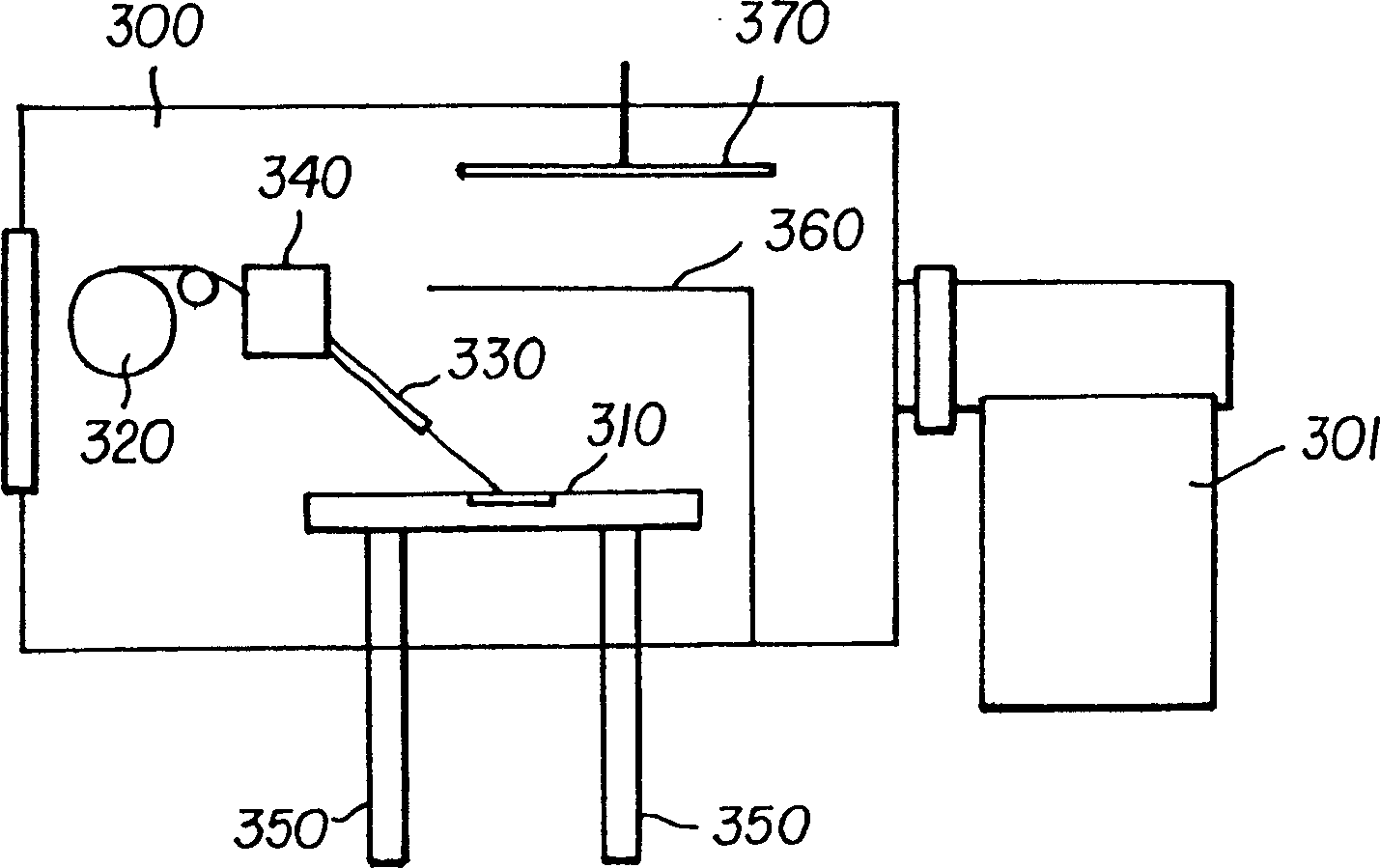
[0044] Four glass substrates are loaded into the loading chamber of the multi-chamber vacuum system. The boron nitride boat of the wire feed vaporization system in the cathode deposition chamber is preheated to about 1000-1100°C, which is higher than the melting point of the wire, and electric power is applied to the boat to bring the Al-Li alloy to the vaporization temperature. The glass substrate was brought into the cathode deposition chamber and placed on a boat with the shutter 306 kept closed. The alloy is fed into a heated boron nitride boat by a reel at a speed of 2 mm / s and a dela...

Embodiment 2

[0049] Organic light-emitting elements are deposited on glass substrates. The substrate consisted of a patterned ITO film (nominal sheet resistance 20 ohm / sq) on Corning 7050 glass. Aluminum tris-8-quinolinol (Alg) was used as the emissive layer. The thickness of the Alg or doped emissive layer is 37.5 nm. A 75nm or 150nm thick NPS layer is used as the HTL layer. Full structural elements were fabricated in a ULVAC multi-chamber Satella UHV system (base pressure 10-6-10-7 Torr). The ULVAC system consists of 7 independent substrate loading chambers for ITO surface pretreatment, organic layer deposition, electrode deposition, and substrate feeding into the dry box through the transfer chamber. Every 10 substrates of 152.4mm×152.4mm is a batch, and it is carried out in batch processing or parallel processing without breaking the vacuum. Substrates are transferred from one station to another by computer-controlled robots.

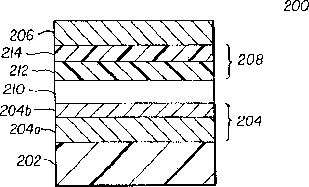
[0050] The structure of the organic light-emitting el...

Embodiment 3

[0058] The preparation of the organic light-emitting element is the same as the element structure described in Example 1, but Li-Al wires with different compositions are used. The raw material composition of the alloy was 97% of Al and 3% of Li. The average excitation voltage and luminosity of these elements were 8.3 volts and 620 cd / m 2 . In this way, raw alloy wire materials with different compositions can be used to prepare the cathode layer of the organic light-emitting element. Other alloy materials such as aluminum-cesium or silver-lithium (Ag-Li) can likewise be used in the form of filaments for the preparation of the cathode layer by the vaporization technique of the present invention.


PUM


Abstract

A method for making an electrode over a light emissive layer in an organic light emitting device includes providing the organic light emitting device into a vacuum chamber having a receptacle for vaporizing material. Heating the receptacle to evaporate material placed in the receptacle for deposition onto the light emissive layer to form the electrode, and a shutter, which when open, permits evaporated material from the heated receptacle to deposit onto the light emissive layer. The method also includes selectively feeding an elongated member made of material to be evaporated into the heated receptacle when the electrode is to be formed and removing such material from such heated receptacle when such electrode is not to be formed.

Description

technical field [0001] The present invention relates to a method of depositing electroluminescent elements, and more particularly, to a method of forming an aluminum-lithium alloy cathode layer in such elements to improve the excitation voltage and efficiency of such elements. Background technique [0002] Organic light-emitting elements are known to be highly efficient and capable of producing a broad spectrum of colors. Its effective application in flat panel displays is attracting attention. [0003] Recent discoveries in the field of organic light emitting element structures have led to elements with an organic EL medium consisting of extremely thin layers (< 1.0 micron combined thickness) separating the anode and cathode. A thin organic EL medium leads to lower resistance, allowing higher current density at a given bias voltage. In a basic two-layer organic light emitting device structure, one organic layer is specifically selected to inject and transfer holes, and...

Claims


Application Information

Patent Timeline
Patent Type & Authority Patents(China)
IPC IPC(8): H05B33/10C23C14/14C23C14/24H01L21/285H01L51/40H01L51/50H01L51/52
CPCH01L51/5221C23C14/246H01L51/0021C23C14/14H10K71/60H10K50/82H05B33/10
Inventor T·K·哈特瓦G·拉杰斯瓦兰
Owner GLOBAL OLED TECH
Why Eureka
Try Eureka