Cutting device

A cutting device, cutting edge technology, used in metal processing machinery parts, maintenance and safety accessories, measuring/indicating equipment, etc., can solve the problems of identifying cutting inserts, lack of flexibility, wiring difficulties, etc., to achieve a clear contrast effect

Active Publication Date: 2007-06-13
DISCO CORP
View PDF1 Cites 13 Cited by
  • Summary
  • Abstract
  • Description
  • Claims
  • Application Information

AI Technical Summary

Problems solved by technology

Therefore, in a configuration in which light is irradiated to the cutting blade and the reflected light is captured, the cutting water is splashed by the high-speed rotation of the cutting blade, and the spray of the cutting water scatters the reflected light, and the cutting blade may not be recognized from the obtained image. , so sometimes it is impossible to detect the chipping, wear, etc. of the cutting insert
[0006] In addition, the light emitted from the light-emitting el

Method used


Image

  • Cutting device
  • Cutting device
  • Cutting device

Examples


Embodiment Construction

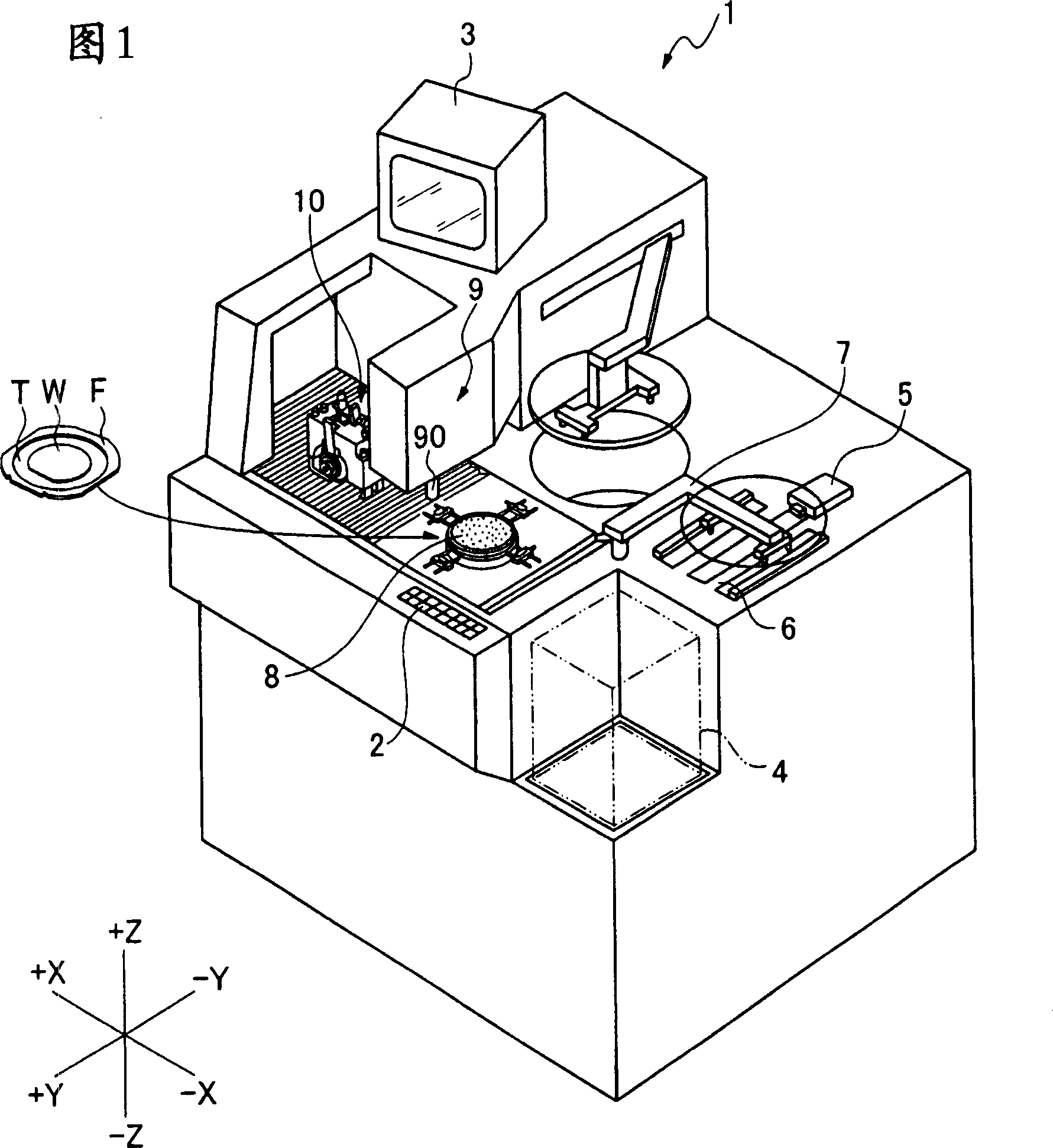
[0031] The cutting device 1 shown in FIG. 1 is a device for cutting a workpiece to be divided into individual chips, and an operation unit 2 for an operator to input various information such as cutting conditions is provided on the front side. In addition, a display unit 3 capable of displaying various information including images is provided on the upper part of the device.

[0032] An example of a workpiece to be cut includes a wafer W shown in FIG. 1 on which a plurality of devices are formed. When cutting the wafer W, the wafer W is attached to the tape T, and the ring-shaped frame F is also attached to the tape T, so that the wafer W and the frame F are integrated through the tape T. In this way, a plurality of wafers W supported by the frame F via the tape T are accommodated in the wafer cassette 4 .

[0033] On the −Y direction side of the wafer cassette 4 is disposed a transport unit 5 that has functions of transporting uncut wafers W from the wafer cassette 4 and sto...


PUM


Abstract

A light emitting unit 109 of cutting insents testing unit 132 for testing cutting blade state of cutting insents and a photography unit 114 is arranged opposited, and fixed on cutting cover 104. As a result of the light emitting unit 109 and the photography unit 114 is arranged opposited, therefore, peripheral shape images which enable identify cutting blade 102a of cutting insents 102 definitely are obtained even if droplets of splashing cutting water existed. Otherwise, through fixing the light emitting unit 109 and the photography unit 114 on the cutting cover 104, thereby without need of using optical fiber and wiring. In this way, a cutting device with functions of photographing for cutting blade of cutting insents, testing imperfects and abrasion gets rid restriction of ligth for photography should use optical fiber wiring, enables hold the state of the cutting insents assuredly to photograph.

Description

technical field [0001] The present invention relates to a cutting device having a cutting blade, and more particularly to a cutting device having a function of detecting the state of chipping and wear of the cutting blade. Background technique [0002] Wafers formed with multiple devices such as LCs and LSIs are cut vertically and horizontally by cutting blades rotating at high speeds, and are divided into individual chips for use in various electronic devices. [0003] The above-mentioned cutting insert is mounted on a high-speed rotating spindle and used, and a cutting edge portion is formed on the outer periphery thereof. The cutting edge portion is formed by fixing abrasive grains made of diamond or the like by means of electroforming, metal bonding, or resin bonding. Therefore, cutting causes the cutting edge portion to deteriorate over time, causing chipping and wear, and there are defects caused by cutting. The problem that the quality of each device deteriorates. ...

Claims


Application Information

Patent Timeline
IPC IPC(8): B23Q17/09B23Q17/24B23Q11/08B23Q11/10
Inventor 关家一马根岸克治米泽昭吉田圭吾
Owner DISCO CORP
Why Eureka
Try Eureka