Heat exchanger

A heat exchanger and heating tube technology, applied in the direction of heat exchange equipment, heat exchanger type, heat exchanger shell, etc., can solve the problems of affecting heat exchange efficiency, reducing heat exchange efficiency, increasing flow rate, etc., to improve heat exchange Benefit, enhance heat exchange effect, increase the effect of flow effect

Inactive Publication Date: 2007-06-13
TECO ELECTRIC AND MACHINERY
View PDF0 Cites 8 Cited by
  • Summary
  • Abstract
  • Description
  • Claims
  • Application Information

AI Technical Summary

Problems solved by technology

[0005] However, according to actual application, when the liquid refrigerant is introduced into the evaporator 7 through the refrigerant pipeline 9, the pore size of the guide hole 731 on the diverter baffle 73 is small, and because the size of the pore size is closely related to the resistance encountered by the fluid ( The smaller the pore diameter, the greater the resistance), so the liquid refrigerant is limited by the pore diameter of the diversion hole 731 to form resistance to reduce the flow rate, and then the contact area between the introduced refrigerant and the surface of the heating tube 75 in the evaporator 7 is limited, and finally affects its heat exchange. benefit
In addition, please refer to Fig. 2, when the imported refrigerant flows out of the pipe and is connected to the inside of the evaporator 7, it is blocked by the diverter baffle 73, that is to say, there is direct resistance directly in front of the refrigerant flow direction, which promotes The refrigerant diverges to both sides and becomes the main flow field of the fluid. On the other hand, because the diameter of the diversion hole 731 on the diversion baffle 73 is too small, the injected refrigerant has no time to pass through the flow diversion hole 731 and flow more toward the diversion baffle. The two sides of the plate 73 flow, and when it flows to the left and right edges of the evaporator 7, because there is no room for the refrigerant to continue to flow to the left or right, the fluid has to rush forward, and the flow between the diverter baffle 73 and the evaporator 7 The flow velocity at the gap 732 formed by the inner wall of the housing 77 increases, which in turn causes the overall flow velocity of the refrigerant to be uneven, and the flow velocity of the refrigerant closest to the diversion holes 731 on the left and right sides will be the fastest
Simultaneously, because the refrigerant is under the situation of nowhere to channel, it is guided into the heating tube 75 tube group through the gap 732 on both sides at an accelerated rate, and due to the introduction of a large amount of refrigerant, the heating tube 75 tube group forms a soaking phenomenon, so that the refrigerant and the heating tube The heat exchange efficiency generated by the 75 rooms is reduced, and finally seriously affects the cooling effect of the chiller

Method used


Image

  • Heat exchanger
  • Heat exchanger
  • Heat exchanger

Examples


Embodiment Construction

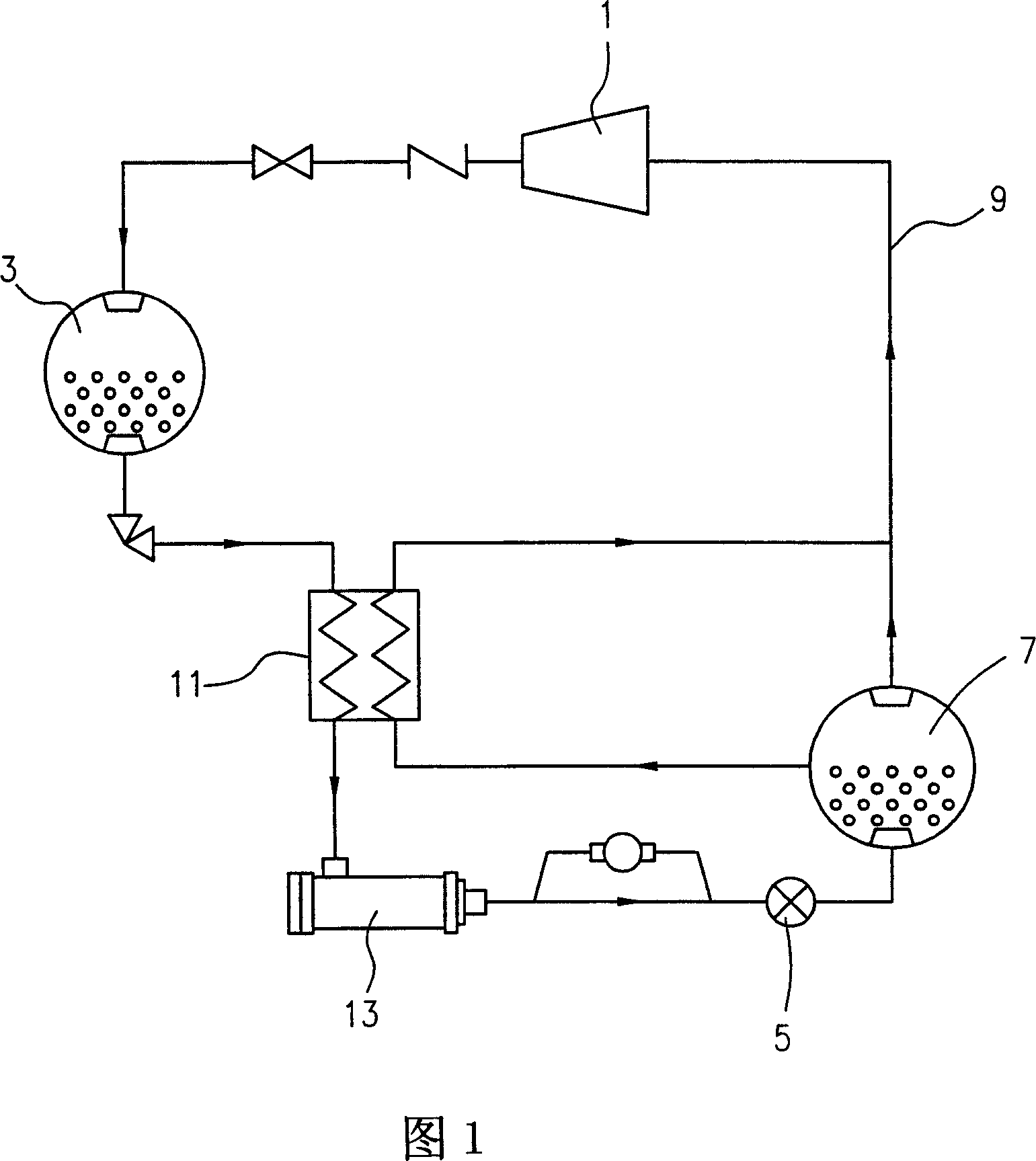
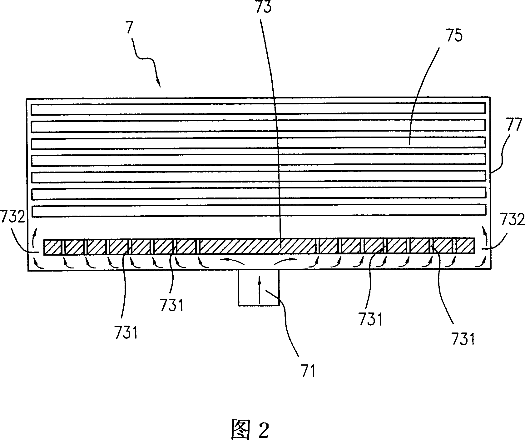
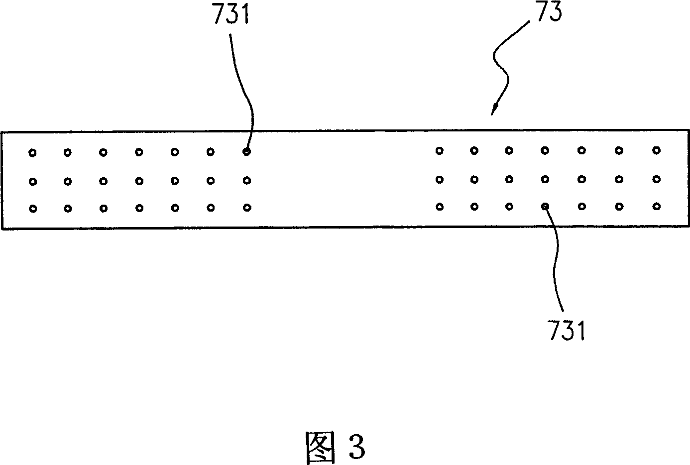
[0051] Please refer to Fig. 4 and Fig. 5 at the same time, wherein, Fig. 4 is a schematic diagram of the internal structure configuration of the flooded evaporator of the present invention, which is used to show the structural configuration when the diverter baffle plate 10 of the present invention is arranged inside the evaporator 7, Fig. 5 Plan view of the splitter baffle 10 of the present invention. The present invention is mainly used in a flooded evaporator 7, but is not limited to a specific chiller or evaporator, and generally belongs to the category of heat exchangers, such as: shell-and-tube heat exchangers, or All kinds of condensers, as long as they must disperse the flow of refrigerant and distribute them evenly on the surface of various types of heating tubes to generate heat exchange effect, they should all belong to the patent application scope of the present invention.

[0052] As shown in the drawings, the same as the known technology, the evaporator 7 of the ...


PUM


Abstract

The invention relates to a heat exchanger that sets at least a distribution diversion baffle at secondary refrigerant intake end of evaporator. By setting diversion mouths at two sides of baffle, the liquid secondary refrigerant would be sent to the intake baffle of evaporator and could be equally flowing into evaporator to increase flow effect in evaporator. Flow boiling effect would be formed in heating pipe to improve heat exchanging benefit of evaporator, and decrease heating pipe quantity. The producing cost would be lowered.

Description

technical field [0001] The present invention relates to a heat exchanger, especially a diversion baffle structure used in a flooded evaporator, which utilizes a number of diversion ports provided on it, and the maximum diameter width of each diversion port has a specific The proportional relationship can improve the heat exchange efficiency of the evaporator. Background technique [0002] Chillers are mainly used in general indoor central air-conditioning systems, and their types can be divided into centrifugal, spiral, reciprocating, and slide-scroll types, such as the compressor of the refrigeration cycle system. Types can be divided into water-cooled, air-cooled, and evaporative-cooled, etc., but if they are distinguished by the type of evaporator, there are two types: direct expansion type and flooded type. [0003] The configuration of the known flooded ice water machine, as shown in Figure 1, includes a compressor 1 for compressing the low-pressure and low-temperature...

Claims


Application Information

Patent Timeline
Patent Type & Authority Applications(China)
IPC IPC(8): F28D5/00F28F9/22
Inventor 陈昭文陈宏民陈腾瑞
Owner TECO ELECTRIC AND MACHINERY
Why Eureka
Try Eureka