
Porous coal rod forming machine nose

A technology of forming machine and porous coal, applied in the field of accessories of coal rod machine, can solve the problems of high cost, unbalanced equipment operation, brittleness, etc., and achieve the effects of enhancing strength and toughness, avoiding overload tripping, and reducing water content

Inactive Publication Date: 2007-06-20
HUBEI YIHUA GRP CO LTD
View PDF0 Cites 0 Cited by
  • Summary
  • Abstract
  • Description
  • Claims
  • Application Information

AI Technical Summary

Problems solved by technology

[0002] The head of the existing coal rod forming machine generally has an integral structure with the shell, the shrinking tray and the rod sleeve, and the discharge holes are arranged on the same circumference in a single way. The head has a simple structure and a single function. amount with operating current much lower than the rated
During use, the discharge hole is easy to be blocked, the operation of the equipment is unbalanced, the coal rod is uneven and fragile, the electric sand is high, the rod sleeve is seriously worn, the maintenance cycle of the machine head is short, the labor intensity of the operator is high, and the cost is high.

Method used


Image

  • Porous coal rod forming machine nose
  • Porous coal rod forming machine nose

Examples


Embodiment Construction

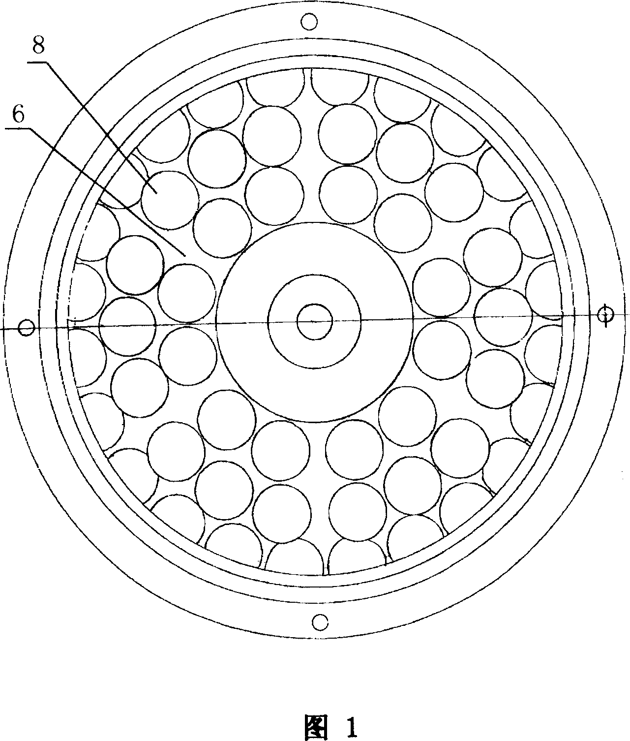
[0010] The present invention adopts the following structure: a machine head of a porous coal rod forming machine, including a casing 1 and a sealing ring 2, the casing 1 is provided with a positioning cover 3 and a shrinking tray 4, and the shrinking tray 4 is evenly distributed along a ring shape There is a grooved discharge area 6, and the grooved discharge area 6 is provided with a discharge hole 8, and the rod sleeve 7 is placed in the rod sleeve support disc 5 in the housing 1 through the discharge hole 8. Discharge holes 8 are distributed on the periphery of the housing 1 .

[0011] When the present invention is made, 12 discharge holes 9 with an inner diameter of 18 mm are evenly distributed on the circumference of the shrinkage plate 4 with a diameter of 150 mm; 24 discharge holes 9 with an internal diameter of 18 mm are evenly distributed on a circumference with a diameter of 216 mm; On the housing 1, 24 discharge holes 9 with an inner diameter of 18 mm are evenly dis...


PUM


Abstract

A working head of porous coal rod forming machine is composed of a casing with locating cover and material compressing tray and a sealing ring. Said material compressing tray has the slot-type discharging regions which are uniformly distributed along a ring and have discharging holes. A rod sleeve passes through said discharging hole. The discharging holes are distributed on the peripheral circumference of said casing.

Description

technical field [0001] The invention relates to an accessory of a coal rod machine, in particular to a machine head of a porous coal rod forming machine used in the nitrogen fertilizer industry for extruding pulverized coal into round rods. Background technique [0002] The head of the existing coal rod forming machine generally has an integral structure with the shell, the shrinking tray and the rod sleeve, and the discharge holes are arranged on the same circumference in a single way. The head has a simple structure and a single function. The amount and operating current are much lower than the rated value. During use, the discharge hole is easily blocked, the operation of the equipment is unbalanced, the coal rod is uneven and fragile, the electric sand is high, the rod sleeve is seriously worn, the maintenance cycle of the machine head is short, the labor intensity of the operator is high, and the cost is high. Contents of the invention [0003] The object of the pres...

Claims


Application Information

Patent Timeline
IPC IPC(8): B30B15/02
Inventor 蒋远华卢光胜
Owner HUBEI YIHUA GRP CO LTD
Learn More